
Cougar V6-153 2.5L DOHC VIN L SFI (2001)
The visible VIN plate, which shows the air bag symbol and either X1 or X2 dependent on the number of air bags fitted, is attached to the windscreen
edge of the instrument panel.
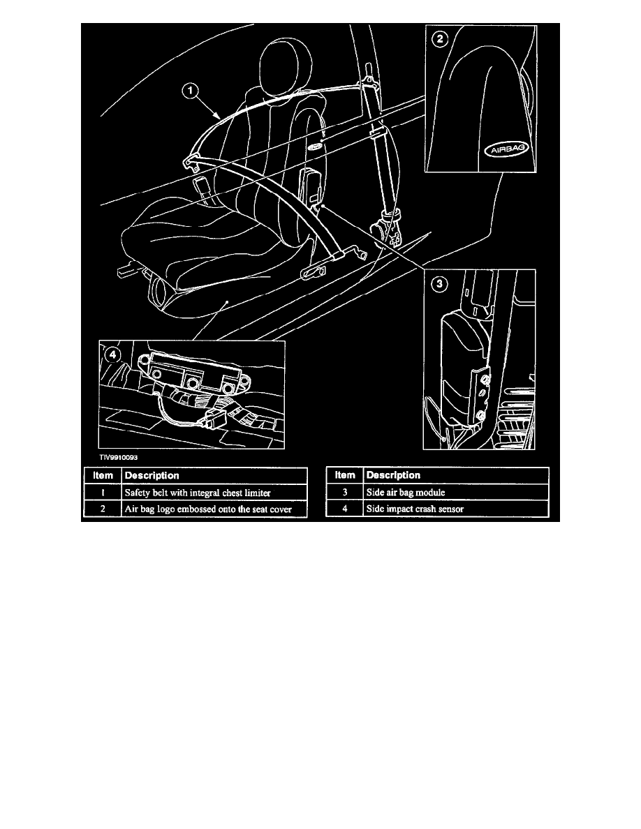
Vehicles equipped with side air bags can be identified by an embossed AIR BAG emblem on the seat fabric adjacent to the air bag module. A label is
attached to the B-pillar adjacent to the seat.
The driver, passenger and side air bag modules consist of the following components which cannot be disassembled:
^
inflator
^
bag
^
container
^
cover
The side air bag module(s) are integrated into the front seat backrests providing an unobtrusive appearance. The unique seat cover has been designed to
accommodate air bag deployment. When the side air bag is deployed the stitched seam of the seat cover adjacent to the side air bag module splits,
allowing the air bag to exit the seat backrest unobstructed.
The purpose of the inflator is to generate the gas needed to fill the air bag. It consists of a high strength steel casing tilled with a solid propellant charge
and an electrically activated igniter. The igniter is activated by a signal from the electronic control module which in turn ignites the propellant charge.
The very rapid burning of the propellant produces sufficient gas to till the air bag(s). As the gases expand they cool, preventing heat damage to the bag.
The drivers air bag module has one inflator and bag, with a filled volume of 55 litres. The passenger air bag module has two inflators and bag having a
tilled volume of 60 litres. The side air bag has a single inflator and a bag with a tilled volume of 12 litres.