
Cougar/XR7 V8-4.6L VIN W (1997)
CAUTION: The rotor runout specification must be met to assure proper brake performance without premature vehicle return with shudder or roughness
complaints.
1. Do not remove wheel and tire.
2. Using a torque wrench tighten lug nuts to 115-142 Nm (85-104 ft. lbs.). Raise and support vehicle.
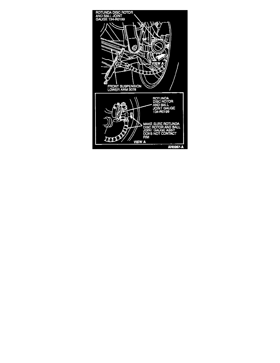
3. Assemble Rotunda Disc Rotor and Ball Joint Gauge or equivalent and extension. Install spherical tip on extension.
4. Locate an opening on inboard side of rotor between disc brake caliper and front disc brake rotor shield.
NOTE: Position Rotunda Disc Rotor and Ball Joint Gauge or equivalent so dial indicator tip is at least 5 mm (3/16 inch) from outer edge of rotor.
5. Clamp Rotunda Disc Rotor and Ball Joint Gauge or equivalent on front suspension lower arm inboard of shock absorber attachment as shown.
Make sure flexible indicator arm and probe tip does not touch dust shield or tire.
NOTE: Do not apply any lateral force on wheel while rotating.
6. Rotate wheel for six revolutions. Record total indicated runout. If the runout is less than 0.076 mm (0.003 inch) runout is satisfactory.