
Cougar/XR7 V8-4.6L VIN W (1997)
Connecting Rod Bearing: Service and Repair
Removal & Installation
REMOVAL
1. Remove oil pan (6675) and oil pump screen cover and tube (6622).
NOTE: Connecting rod caps, connecting rods (6200) and connecting rod bearings (6211) should be numbered to make sure they are assembled in
their original positions.
2. Turn crankshaft (6303) until connecting rod bearing to be removed is accessible. If more than one connecting rod bearing is being removed,
identify the connecting rod caps, connecting rods and connecting rod bearings for cylinder position.
3. Remove the connecting rod cap, lower connecting rod bearing and upper connecting rod bearing. Keep cap and connecting rod bearings together.
Use care to prevent damage to the bearing, cylinder bore and crankshaft surfaces.
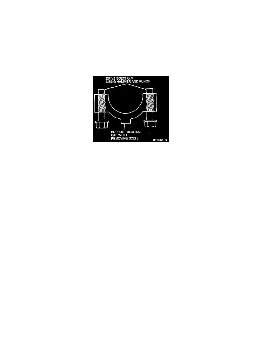
4. Connecting rod bolts (6214) are retained in the connecting rod cap hole with a light press fit. The connecting rod bolts have been torqued to yield
at least twice and must be discarded. Use a. hammer and punch to drive connecting rod bolts from connecting rod cap.
CAUTION: Care should be taken not to damage the fractured rod and cap joint face surfaces or possible damage to engine may occur.
5. Inspect the connecting rods, connecting rod caps and crankshaft.
INSTALLATION
1. Clean crankshaft connecting rod journals with a clean cloth.
2. Lubricate crankshaft and connecting rod bearing surfaces with clean engine oil meeting Ford specification WSS-M2C910-A1.
3. Install upper connecting rod bearings in the connecting rod. Align retaining tang of connecting rod bearing with notch in connecting rod.
CAUTION: Be sure not to scratch cylinder wall or crankshaft journal with connecting rod. Pull piston (6108) down until connecting rod bearing
seats on crankshaft journal.
4. Install lower connecting rod bearings in the connecting rod caps. Align retaining tang of connecting rod bearing with notch in connecting rod cap.
NOTE: Due to the use of a cracked connecting rod joint face surface, the connecting rod cap must be properly aligned to the connecting rod. The
connecting rod and connecting rod cap bearing tangs should be located on the same side of the connecting rod.
5. Alternately tighten connecting rod cap bolts in three steps:
a. Tighten to 40-45 Nm (30-33 ft. lbs.).
b. Tighten an additional 90-120°.
NOTE: After all connecting rod cap bolts are tightened to specification, rotate the crankshaft to make sure of smooth operation.