
Cougar/XR7 V8-4.6L VIN W (1997)
Valve Cover: Service and Repair
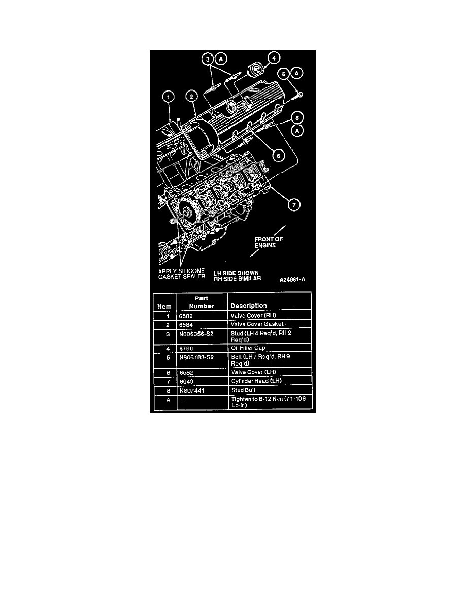
Right Side
REMOVAL
1. Disconnect negative battery ground cable (14301).
2. Remove air cleaner outlet tube (9B659).
3. Disconnect 42-pin connector and 8-pin connector leading to the mass air flow sensor (MAF)(12B579) and intake air temperature sensor (IAT)
(12A697).
4. Remove nut retaining A/C line to the RH front fender apron (16054).
5. Lift A/C line and feed the 42-pin connector under the line. Position 42-pin connector out of the way.
6. Relieve fuel system pressure and disconnect fuel lines.
CAUTION: Do not pull on the ignition wires, as ignition wire may separate from the connector in the ignition wire boot.
7. Disconnect ignition wires from spark plugs (12405).
8. Remove ignition wires and ignition wire separators (12297) from valve cover studs and position ignition wires out of the way.
9. Remove positive crankcase ventilation valve (PCV)(6A666) from crankcase ventilation grommet (6A892) and position out of the way.
10. Remove bolts and stud bolts retaining valve cover (6582) to cylinder head (6049). Remove valve cover.
INSTALLATION
1. Remove all traces of dirt, on or previously applied sealant from the sealing surfaces.
2. Clean all sealing surfaces with Metal Surface Cleaner F4AZ-19A536-RA or equivalent meeting Ford specification WSE-M5B392-A. Sealing
surfaces must be clean and dry before applying sealant.