
Cougar/XR7 V8-4.6L VIN W (1997)
Control Assembly: Description and Operation
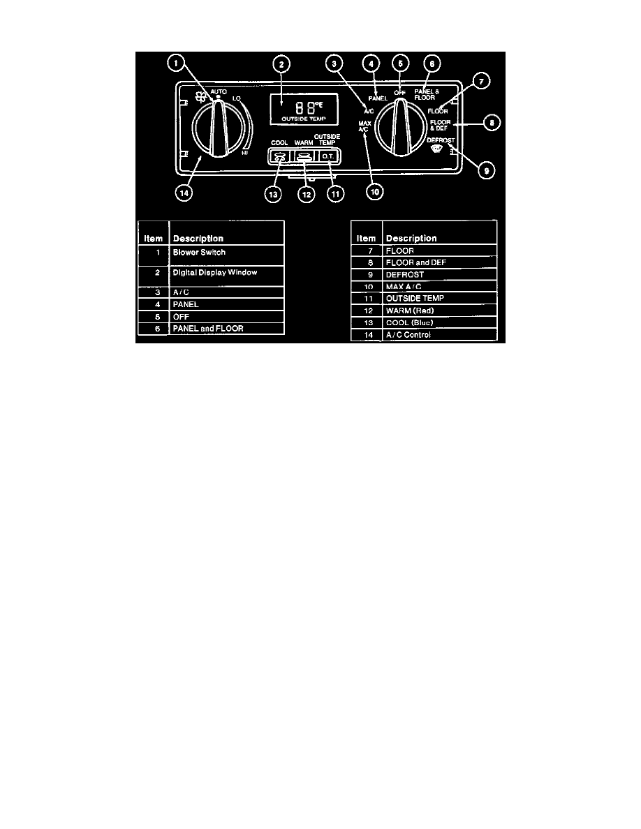
Control Assembly
The semi automatic temperature control assembly is located in the instrument panel and consists of:
^
an eight-function rotary selector valve.
^
two temperature-selecting push buttons.
^
an outside temperature button.
^
a variable blower speed knob.
^
a Vacuum Fluorescent Display (VFD) for displaying the selected temperature and diagnostic codes.
The center area of the control assembly is the vacuum fluorescent display window.
^
The display will show the selected temperature to which the components of the control system will respond.
^
The display will also show outside temperature for four seconds (if selected).
^
A/C blower motor speed, under automatic control, varies in response to ambient temperature changes and a predetermined delay factor.
Temperature selection may be increased or decreased in one degree increments between 18°C (65°F) and 29°C (85°F).
^
Pressing the WARM (red) button will raise the temperature.
^
Pressing the COOL (blue) button will lower the temperature. The system's automatic control will respond accordingly.
The control assembly also has a 16°C (60°F) setting for maximum cooling and a 32°C (90°F) setting for maximum heat.
When the function selector is turned to the OFF position, the system will apply vacuum to close the heater and A/C air inlet duct door to prevent ram air
from entering the vehicle and will also stop A/C blower motor operation.
Under automatic (auto) control, the A/C blower motor speed will vary as required to accommodate the total automatic functions of the system. When the
blower knob is not at the AUTO position, the A/C blower motor speed is constant and based on the position (setting) of the knob.
Illumination bulbs in the control assembly provide backlighting for the nomenclature around the blower switch, function selector switch and on the
buttons.
^
The intensity of the light from these bulbs will increase or decrease with the cluster illumination when the headlamp switch knob and shaft is
adjusted. The vacuum fluorescent display will also dim with the instrument cluster and control nomenclature lights.
The A/C control will display the set temperature in either °F or °C. To change the display, set the function selector knob at MAX A/C and rotate the Fan
knob to the HI position. Then, simultaneously press the COOL, WARM and OUTSIDE TEMP buttons and hold depressed for 3/4 second before
releasing.