
Cougar/XR7 V8-4.6L VIN W (1997)
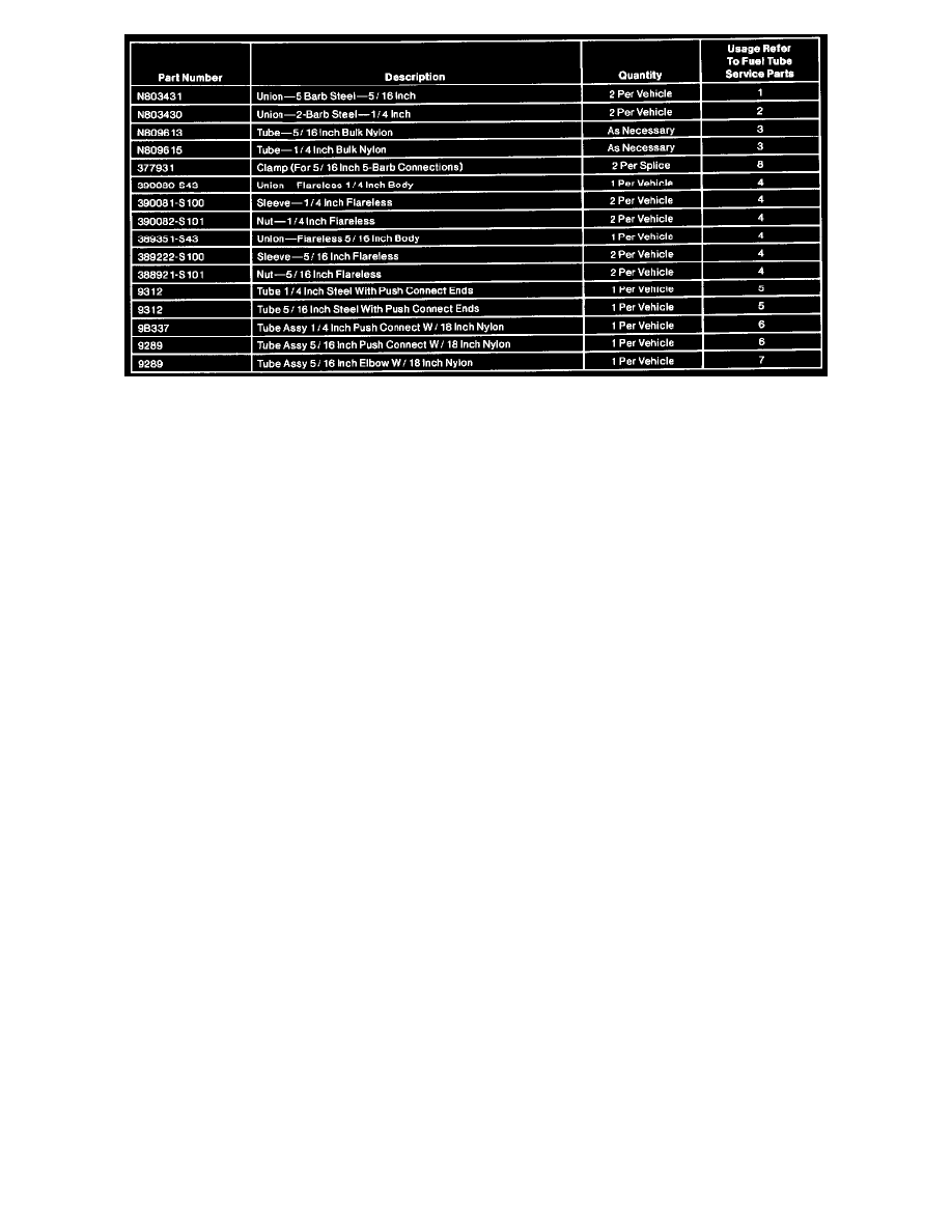
Splicing Service Combinations (Part 2 Of 2)
SERVICE NOTES
Fuel injection systems are equipped with an electric fuel pump that provides fuel to the engine at higher pressure than conventional fuel systems.
Refer to fuel pump module for service. A fuel return system is also provided. All fuel hose/tube connections are made with push connect fittings
and all hoses are serviced as assemblies.
All replacement hoses MUST be serviced as assemblies. Bulk fuel hose must not be used to service tubing in high-pressure fuel systems.
SPLICING NYLON to NYLON
1. Perform fuel pressure release procedure.
2. Drain fuel tank if necessary.
3. Cut a section of service tubing (type 11 or 12 nylon available in 1/4 and 5/16-inch sizes) to the same length as the damaged section of tubing.
4. Select the proper (1/4 or 5/16-inch) barbed connectors for completing the splice. Two connectors are required for each splice.
CAUTION: Do not use any heating method except hot water to repair nylon tubing. Temperatures above 100°C (212°F) cause the nylon to
soften and will not seal on the barbed connectors. Replacing nylon line In the engine compartment requires heat protective Hypalon hose.
NOTE: To make hand-insertion of the barbed connectors into the nylon easier, the tube end must be soaked in a cup of boiling water for one
minute immediately before pushing the barbs into the nylon. The 5/16-inch barbed connector is used for splicing 5/16-inch non EFI and 5/16-inch
EFI tubing.
5. Install the barbed connectors into each end of the replacement tubing using boiling water.
6. Install clips onto any tubes which might be difficult to access once the final splices are completed.
7. Install four keystone clamps loosely onto the original nylon tubing before beginning Step 8.
8. Complete the splice of the replacement nylon to the original nylon tubing at both ends as shown in the illustration.
9. Tighten the clamps in the locations shown in the illustration.
10. Install any remaining clips which were removed for service and check that the tubes are secured in the original clips.
11. Fill fuel tank, start engine and check for leaks.