
Cougar/XR7 V8-4.6L VIN W (1997)
Safing Sensor: Service and Repair
REMOVAL
1. Record USER 1 and USER 2 preset radio frequencies.
2. Disconnect battery ground cable. Wait one minute for backup power supply energy to be depleted.
WARNING: The electrical circuit necessary for system deployment is powered directly from the battery. To avoid accidental deployment
and possible personal injury, the battery ground cable must be disconnected prior to servicing or replacing any system components.
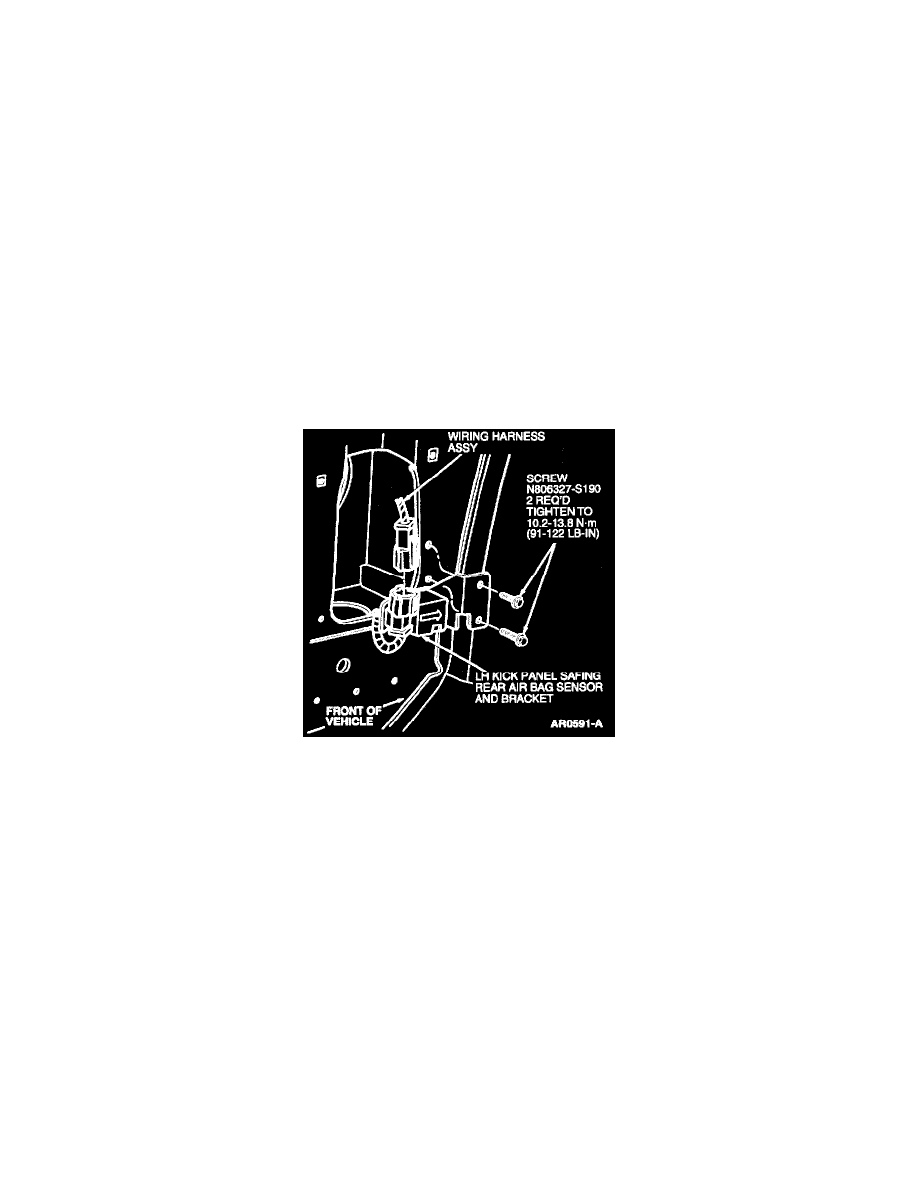
3. Remove LH cowl side trim panel. Remove one screw and pull wiring and cover assembly to the side to gain access to LH kick panel safing sensor.
NOTE: To service stripped LH kick panel safing sensor retaining screws, replace old screws with 14 mm self-tapping screws. Tighten to
10.2-13.8 Nm (91-122 lb in).
4. Remove two screws retaining LH kick panel safing rear air bag sensor and bracket to LH cowl side panel.
5. Detach LH kick panel safing sensor connector from LH kick panel safing sensor bracket.
6. Disconnect LH kick panel safing sensor wiring connector from body main wiring connector.
INSTALLATION
1. Position LH kick panel safing rear air bag sensor and bracket to LH cowl side panel.
2. Connect LH kick panel safing sensor wiring connector to body main wiring connector.
3. Attach LH kick panel safing sensor connector to the LH kick panel safing sensor bracket.
4. Secure LH kick panel safing rear air bag sensor and bracket with two LH kick panel-to-cowl side panel screws. Tighten to 10.2-13.8 Nm (91-122
lb in).
5. Attach wiring and cover assembly and install LH cowl side trim panel.
6. Reconnect battery ground cable.
7. Prove out air bag system.
8. Reprogram USER 1 and USER 2 preset radio frequencies and set clock.