
Cougar/XR7 V8-4.6L VIN W (1997)
Drive/Propeller Shaft: Service and Repair
Installation
1. Lubricate the driveshaft slip yoke splines with Premium Long-Life Grease XG-1-C or -K or equivalent meeting Ford specification ESA-M1C75-B.
Remove the plug from the transmission extension. Inspect the housing seal for damage; replace if required.
2. Align driveshaft slip yoke index paint mark with transmission output shaft paint mark and install the driveshaft assembly. Do not allow the
driveshaft slip yoke to bottom on the output shaft with excessive force.
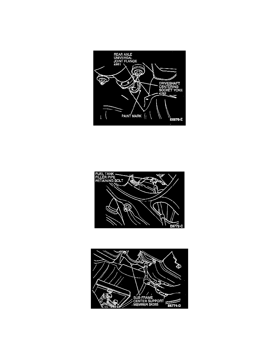
3. Align marks on driveshaft centering socket yoke with rear axle universal joint flange. Install and tighten four retaining bolts to 95-130 Nm (70-95
ft. lbs.).
NOTE: When installing a new driveshaft, align factory-made yellow paint mark at rear of driveshaft tube with factory-made yellow paint mark on
outside diameter of rear axle universal joint flange. If paint marks are not visible.
4. Raise fuel tank and install fuel tank support straps. Tighten retaining bolts to 29-41 Nm (22-30 ft. lbs.).
5. Install fuel tank filler pipe retaining bolt. Tighten retaining bolt to 2.7-3.7 Nm (24-32 in. lbs.).
6. Install sub-frame crossmember. Tighten two retaining bolts to 20-30 Nm (15-22 ft. lbs.).
7. Install sub-frame center support member on forward side of fuel tank. Tighten bolts to 20-30 Nm (15-22 ft. lbs.).