
Grand Marquis V8-281 4.6L SOHC (1992)
b.
Mark the outline of the shield center mounting tab against the raised interference point on the back of the adapter assembly; this will have to
be ground flat to allow the shield to fit properly upon final installation.
5.
Remove the "C" clamp, loosen the bottom nut 2 or 3 turns and allow the shield to hang from the stud or remove the shield from the adapter.
6.
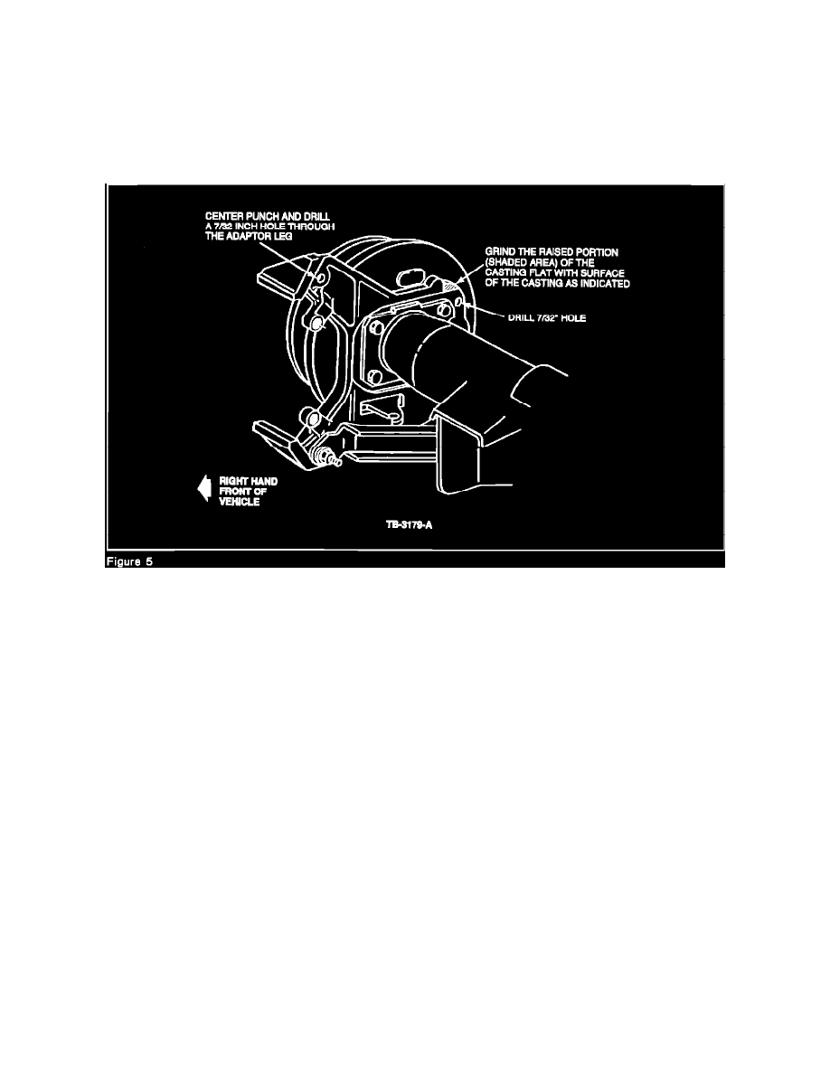
Center punch the middle of the circle previously marked around the "C" clamp and drill a 7/32" hole through the adapter leg.
a.
Grind the raised portion of the casting (on the back side of the adapter) flat with the surface.
b.
Remove stock beyond the mark to allow sufficient clearance for the center tab to fit flat against the adapter (Figure 5).
7.
Place the shield upper mounting tab over the hole, and proceed as follows:
a.
Start a self-tapping mounting screw to permit proper location, then carefully inspect the area previously ground to assure flat mounting of
the center tab to the back of the adapter.
b.
Grind additional material as required to provide a flat, non-interfering fit.
8.
Tighten the nut to 23 N-m (17 lb.ft.) and tighten the self-tapping upper screw to 15 N-m (11 lb.ft.)
9.
On the left side, remove the jounce bumper from the axle assembly. This is not required on the right side.
a.
Center punch the drill location through the center tab hole.
b.
Drill the center mounting hole in three steps to prevent damage to the inside of the adapter plate: begin with a 1/16" (1.59 mm) drill, follow
with a 1/8" (3.18 mm) drill and finish with a 7/32" (5.56 mm) drill. Install a self-tapping screw and tighten to 15 N-m (11 lb.ft.).
NOTE:
IF THE VEHICLE IS NON-ABS, MAKE SURE THAT THE CENTER TAB DOES NOT INTERFERE WITH THE SENSOR HOLE PLUG,
PREVENTING PROPER FLAT ATTACHMENT.
10.
Using brake cleaning solvent spray, remove all metal chips that may be present. If unit is equipped with ABS, wipe off the wheel speed sensor and
inspect for metal shavings; clean further if required. Install sensor and tighten the mounting screw to 4.5-7 N-m (3-5 lb.ft.).
11.
Install rotor.
a.
Remove caliper pins and wipe the pins and the pin bushing interiors clean of any debris. Install a coating of silicone dielectric compound
D7AZ-19A331-A, (Motorcraft WA 10 or equivalent) to the pin surfaces.