
Grand Marquis V8-281 4.6L SOHC (1992)
ensure all other causes have been addressed and corrected before continuing.
STEP 4
a. A constant tone, solid light or "STO LO" readout means base idle rpm is within range. To exit test, unlatch STI button, then wait 4 seconds for
reinitialization (after 10 minutes it will exit by itself).
b. Beeping tone, flashing light, or "STO LO" readout at (8hz) indicates Throttle Position Sensor is out of range due to over adjustment; adjustment
may be required.
c. Beeping tone, flashing light, or "STO LO" readout at (4Hz) indicates base idle rpm is too fast, adjustment is required, go to STEP 6.
d. Beeping tone, flashing light, or "STO LO" readout at (1Hz) indicates base idle is too low, adjustment is required, go to STEP 5.
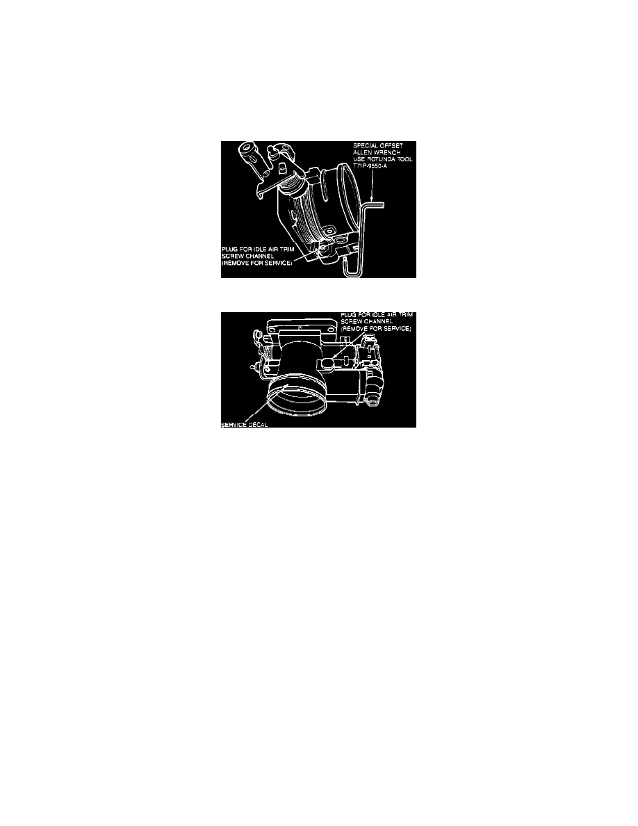
Idle Air Trim Screw
Air Trim Screw Channel Cover
STEP 5
DO NOT clean the throttle body turn the air trim screw counterclockwise until conditions in Step 4(a) are satisfied. Process completed.
STEP 6
DO NOT clean the throttle body, turn the air trim screw clockwise until conditions in step 4(a) are satisfied.
THROTTLE BODY ORIFICE PLUG INSTALLATION
1. Remove air inlet tube(s) from throttle body.
2. Select the proper color plug by using the Go/No-Go gauge pegs, included with the service kit.
3. Starting with the largest diameter gauge peg, attempt to insert it through the throttle plate orifice.
4. If gauge peg goes through the orifice, use the corresponding colored plug. If gauge peg does not go through, proceed with the next smaller gauge
peg for Go/No-Go Test.
NOTE: It is important that the largest Go/No-Go combination is used in determining the proper plug size.
5. If the smallest gauge peg does not go through the orifice, use the reamer bit and handle, included with the service kit, to enlarge the plate orifice.
Wipe bearing grease on both sides of the plate orifice and on the reamer bit to hold the brass chips. After reaming, wipe plate clean, then return to
Step 3 to determine the proper plug size.
6. Using the installation tool from the service kit, push the plug into the orifice until it bottoms out at the throttle plate.
7. Open and snap closed the throttle several times to verify proper plug retention.
8. Reconnect the air inlet tube(s).
9. Reset idle rpm per engine requirement, using the throttle plate stop screw.