
Grand Marquis V8-281 4.6L SOHC (1992)
Throttle Valve Cable/Linkage: Adjustments
With AOD
At Transmission
ADJUST
1. On vehicles without Idle Speed Control (ISC), proceed as follows:
a. Check and adjust curb idle speed to specifications with and without throttle solenoid positioner (anti-dieseling solenoid energized, if
equipped).
b. Shut off engine and remove air cleaner.
c. De-cam fast idle cam on so that throttle lever is against idle stop or throttle solenoid positioner stop.
2. Place shift lever in Neutral and apply parking brake.
3. Set linkage lever adjustment screw at approximately mid-range.
4. If a new TV control rod assembly is being installed, connect rod to linkage lever at throttle body.
5. Raise and support vehicle.
6. Loosen bolt on sliding trunnion block on TV control rod assembly, removing any corrosion from control rod and freeing up trunnion block so that
it slides freely on control rod.
7. Push up on lower end of control rod to ensure linkage lever on throttle body is firmly against throttle lever, then release force on rod and ensure
rod stays up.
8. Push TV control lever on transmission up against its internal stop with a force of approximately five lbs and tighten bolt on trunnion block.
NOTE: Do not relax force on lever until bolt is tightened.
9. Lower vehicle and ensure throttle lever is still against stop and if not, repeat steps 2 through 9.
At Throttle Body
ADJUST
1. Position throttle lever at idle stop, place shift lever in Neutral, and apply parking brake (engine OFF).
2. Turn linkage lever adjusting screw counterclockwise until end of screw is flush with throttle lever face
3. Turn adjusting screw clockwise to provide 0.005 inch clearance between end of screw and throttle lever. Continue turning adjusting screw an
additional three turns.
NOTE: If screw travel is limited, one turn is acceptable.
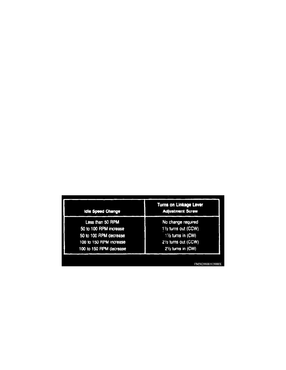
Idle Speed/Throttle Valve Linkage Adjustment Chart
4. Whenever idle speed is adjusted by more than 50 RPM, the adjustment screw on the linkage lever at the throttle body should also be adjusted as
listed in the Idle Speed/Throttle Valve Linkage Adjustment Chart.
NOTE: If idle speed was adjusted, ensure 0.005 inch clearance exists between linkage lever adjusting screw and the throttle lever. The throttle
lever should be at the idle stop and the shift lever in Neutral.
Throttle Rod Linkage
ADJUST TV ROD LINKAGE
1. Check curb idle speed, adjusting as necessary. Ensure curb idle speed is set to specification with and without the throttle solenoid positioner
(anti-diesel solenoid) energized, if equipped.
2. Using adapter fitting D80L-77001 -A or equivalent, attach suitable pressure gauge to TV port on transmission, using enough flexible hose so that
gauge can be read while operating engine.