
Grand Marquis V8-302 5.0L VIN F FI (1985)
Control Arm: Service and Repair
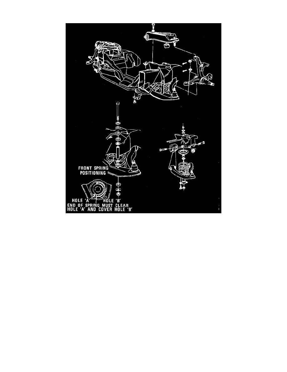
Fig. 2 Typical Front Suspension
LOWER CONTROL ARM
1.
Raise and support front of vehicle, then remove front wheels.
2.
Remove brake caliper, rotor and dust shield.
3.
Remove jounce bumper, if equipped.
4.
Remove shock absorber.
5.
Disconnect stabilizer bar link from lower control arm.
6.
Disconnect steering center link from pitman arm.
7.
Remove lower ball joint attaching nut cotter pin, then loosen lower ball joint nut one or two turns. Do not remove nut from stud at this time.
8.
Install ball joint press tool T57P-3006-B or equivalent between upper and lower ball joint studs.
9.
Compress ball joint with tool, then tap spindle, near lower stud, to loosen stud in spindle.
10.
Remove ball joint press tool, then position a suitable jack under lower control arm.
11.
Install suitable coil spring compression tool, then remove coil spring.
12.
Remove ball joint nut, then the lower control arm assembly.
13.
Reverse procedure to install, noting the following:
a. Torque ball joint attaching nut to 100---120 ft. lbs.
b. Ensure coil spring is properly aligned, Fig. 2.
c. Torque control arm-to-crossmember attaching bolts and nuts to 100---140 ft. lbs.
d. Check wheel alignment, refer to ``Wheel Alignment Section.''
UPPER CONTROL ARM
1.
Raise and support front of vehicle, then remove front wheels.
2.
Remove upper ball joint attaching nut cotter pin, then loosen upper ball joint nut one or two turns. Do not remove nut from stud at this time.
3.
Install ball joint press tool T57P-3006-B or equivalent between upper and lower ball joint studs.