
Grand Marquis V8-302 5.0L VIN F TBI (1984)
Brake Shoe: Service and Repair
Installation
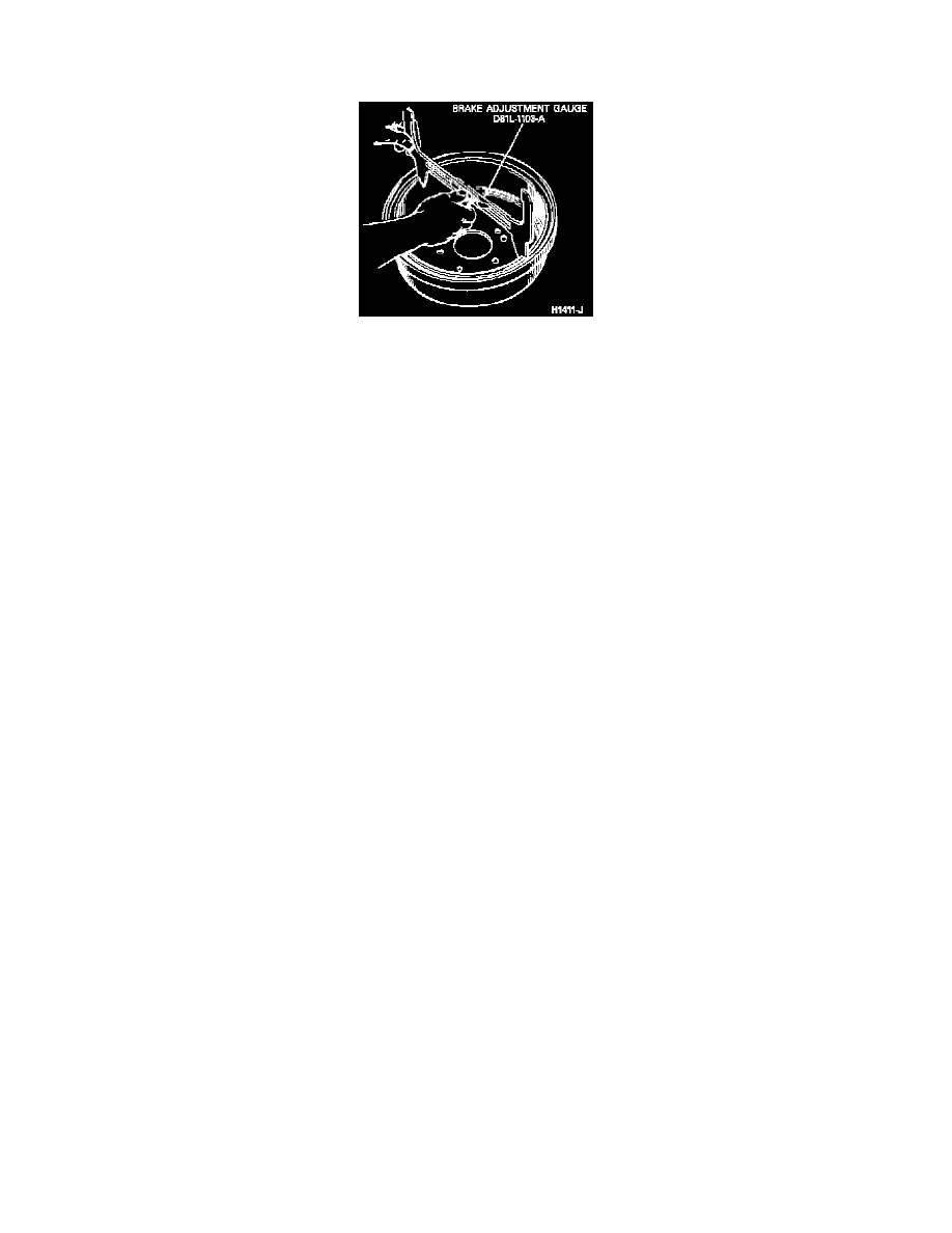
Brake Adjustment Gauge
1.
Lightly lubricate backing plate shoe contact surfaces with suitable brake lube.
2.
On type 1 brakes, assemble parking brake lever to secondary shoe and secure with spring washer and retaining clip. Crimp ends of clip with
suitable pliers. On type 2 brakes, engage parking brake lever tang with secondary shoe.
3.
Position brake shoes on backing plate, primary (short lining) shoe facing front of vehicle and secondary (long lining) facing rear. Secure brake
shoes with hold-down springs, pins and retainers.
4.
Install parking brake link and spring between shoes.
5.
Loosen parking brake adjustment nut, then install parking brake cable on parking brake lever.
6.
Install shoe guide plate and adjuster cable eyelet on anchor. Ensure adjuster cable crimp faces out.
7.
Ensure parking brake link is properly positioned between brake shoes and wheel cylinder links are engaged in shoe web.
8.
Using suitable brake spring pliers, install primary return spring from brake shoe to anchor, then secondary return spring from brake shoe to anchor.
9.
On all types, remove wheel cylinder clamp installed during removal of brake shoes.
10.
Tighten adjuster screw assembly to thread limit and back off {1-2} turn.
11.
Install adjuster screw assembly between shoes. Ensure toothed wheel is on secondary shoe side. Adjuster screw assemblies are stamped R
(right) and L (left). To ensure proper adjuster operation, they must be installed on their respective sides.
12.
Hook adjuster cable hook into adjuster lever hole, then position adjuster spring hook in large hole in primary shoe web. Using suitable brake
spring pliers, install adjuster spring in adjuster lever hole.
13.
Ensure adjuster cable is properly seated in cable guide, then pull adjuster lever, cable and adjuster spring down and towards the rear, engaging
lever pivot hook in the large hole of secondary shoe web.
14.
After installation, check adjuster operation by pulling adjuster cable between cable guide and adjuster lever towards secondary shoe sufficiently to
lift adjuster lever past one tooth on adjuster screw assembly. The adjuster lever should snap into position behind the next tooth, then upon release
of adjuster cable, rotate toothed wheel one notch. If operation is not satisfactory, recheck installation.
15.
Ensure brake shoe upper ends are seated against anchor pin and shoe assemblies are centered on backing plate. If not, back off parking brake
adjustment.
16.
Using suitable brake drum to shoe gauge, Fig. 3, measure brake drum inside diameter. Adjust brake shoes to dimension obtained on outside
portion of gauge using adjuster screw.
17.
Install brake drum, wheel and tire assembly.
18.
If any hydraulic brake connections have been opened, perform system brake bleeding procedures.
19.
Adjust parking brake. Refer to individual car chapter for procedures.
20.
Inspect all hydraulic lines and connections for leakage and repair as necessary.
21.
Check master cylinder fluid level and replenish as necessary.
22.
Check brake pedal for proper feel and return.
23.
Lower vehicle and road test. Do not severely apply brakes immediately after installation of new brake linings or permanent damage may
occur to linings, and/or brake drums may become scored. Brakes must be used moderately during first several hundred miles of operation
to ensure proper burnishing of linings.