
Grand Marquis V8-302 5.0L VIN F TBI (1984)
Blower Motor: Testing and Inspection
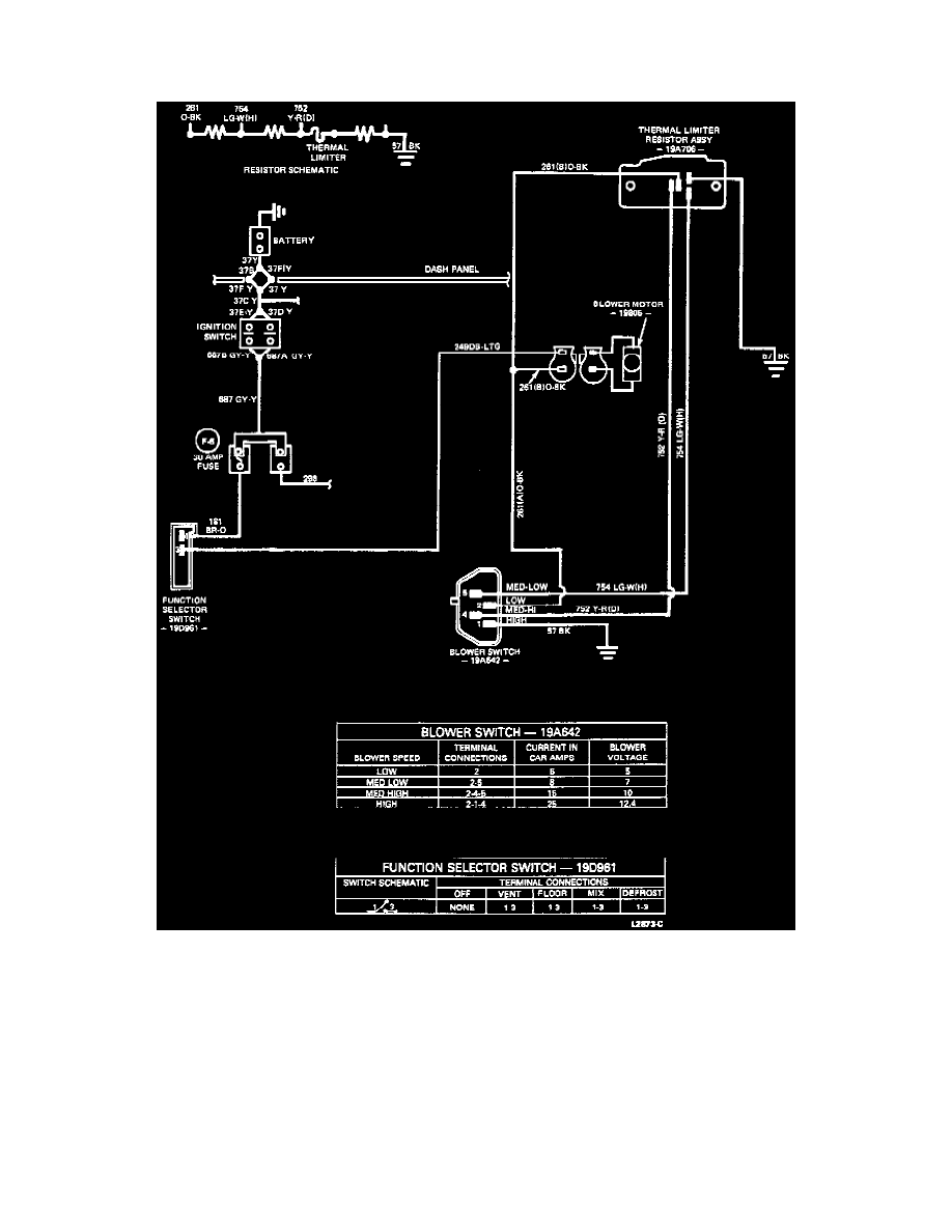
Blower Ground-Side Switching Circuit Test
Heater System Electrical Wiring Diagram And Continuity Test
NOTE: Amperage readings, on the blower motor circuit, will increase as the blower speed is increased. This is the same as on previous supply
switching circuits or previous model vehicles.
Voltage readings, on the blower circuit of the ground side switching circuits, decrease instead of increasing as the blower speed is increased. The
orange-black 261 circuit will always read the same voltage as battery positive (+) voltage and the black 57 circuit voltage will decrease with each
increase in blower speed. A maximum blower speed switch position will produce a zero voltage reading as a result of the blower speed switch by-passing
the resistor assembly and connecting the blower's negative (-) black 57 circuit directly to ground.