
Grand Marquis V8-302 5.0L VIN F TBI (1984)
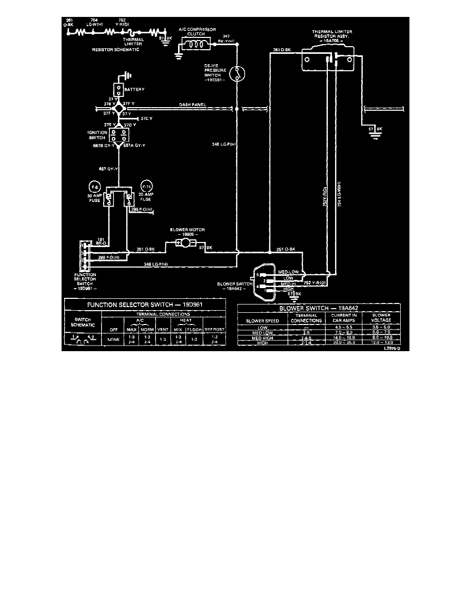
A/C-Heater System Electrical Wiring Diagram And Continuity Test
System Airflow
These images contain system vacuum schematics and vacuum motor charts which illustrate vacuum routings and airflow during the various system
conditions.
OFF
In OFF position the outside-recirculate air door is in the recirculating air position. The panel door is in the no vacuum position, and the
floor-defrost door is in the FLOOR (full vacuum) position. The blower is off and the temperature blend door maintains a position depending on the
temperature control lever position.
MAX-A/C Recirculate
With the function lever in the Max-A/C position, the outside-recirculate air door is closed to outside air (vacuum) and the passenger compartment
air is recirculated through the system. The panel door is in the panel position (vacuum) and the air is distributed out of the instrument panel
registers. The floor-defrost door is also applied with vacuum, directing a small amount of air to the floor area. The recirculating air can be heated
to a higher desired temperature by moving the temperature lever toward WARM.
NORM-A/C Outside Air
When the function lever is in the NORM-A/C position, the outside-recirculate air door is opened to admit outside air into the system (no vacuum).
All other doors are positioned the same as in the MAX-A/C position with the temperature controlled in the same manner.
VENT
In VENT position, outside air is directed through the instrument panel registers with manual control of the discharge air temperatures in the same
manner as MAX- A/C and NORM-A/C, however, refrigerated cooling is not available. VENT, and FLOOR positions provide the most economical
operations because the compressor does not operate.