
Grand Marquis V8-351 5.8L (1982)
Steering Gear: Adjustments
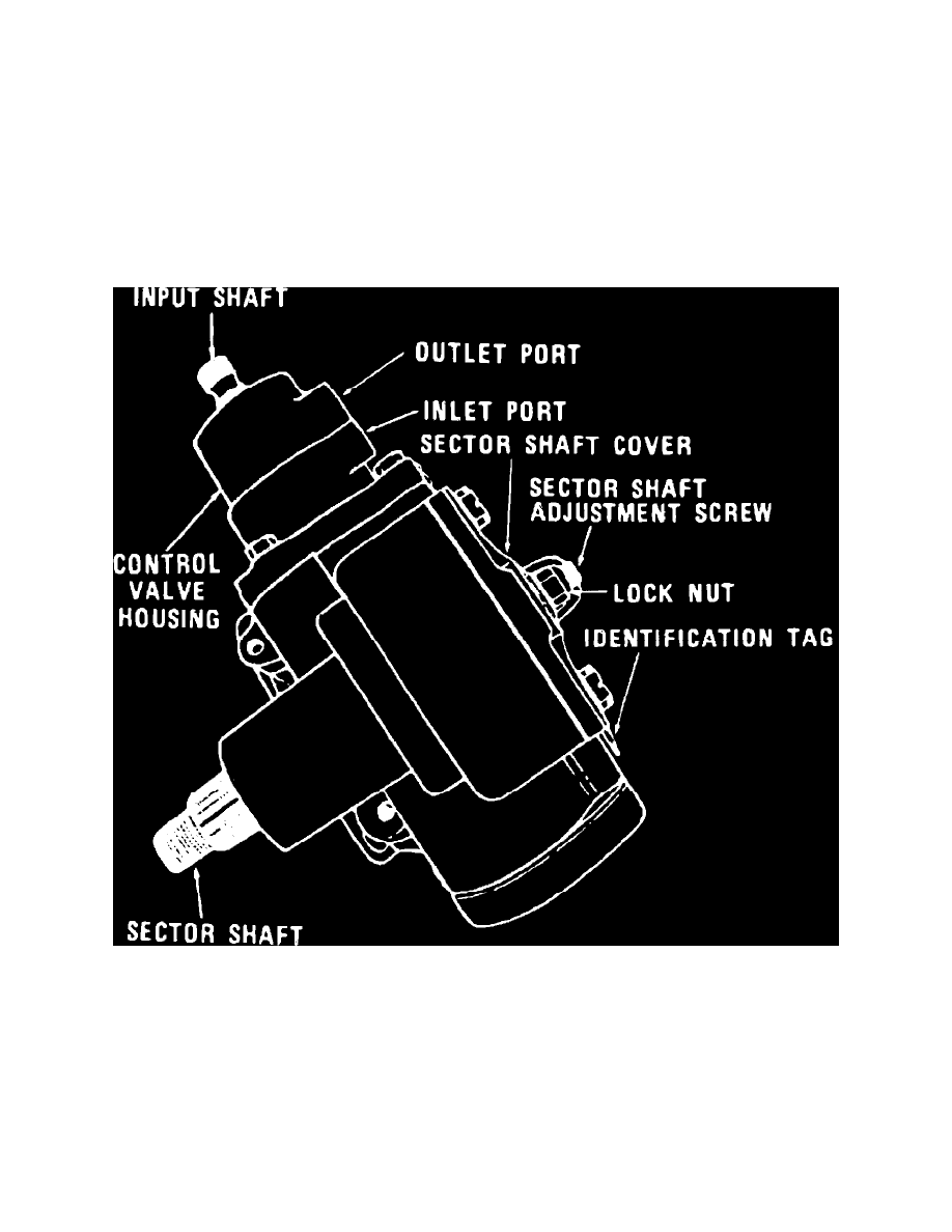
VALVE SPOOL CENTERING CHECK
The ``out-of-car'' procedure for valve centering check is the same as for the ``in-car'' except the torque and simultaneous pressure reading must be
made at the right and left stops instead of either side of center.
1.
Install a 2000 psi pressure gauge in pressure line between pump outlet port and steering gear inlet port. Make sure that valve on gauge in is fully
open position.
2.
Check fluid level in reservoir and replenish as required.
3.
Start engine and cycle steering wheel from stop-to-stop to bring steering lubricant up to normal operating temperature. Stop engine and recheck
reservoir. Add fluid as necessary.
4.
With engine running at a fast idle speed (1000 RPM) and steering wheel centered, attach an inch-pound torque wrench to steering wheel retaining
nut. Apply sufficient torque to wrench in each direction (either side of center) to get a gauge reading of 250 psi.
5.
The torque reading should be the same in both directions. If the difference between readings exceed 4 inch lbs., the shaft and control assemblies
must be replaced.
Fig. 2 Adjusting mesh load
STEERING GEAR ADJUSTMENTS
Preload (thrust bearing adjustment) and worm-to-rack preload cannot be changed in service. The only adjustment that can be performed is the total
over-center position load to eliminate excessive lash between sector and rack teeth.
1.
Disconnect pitman arm from sector shaft.
2.
Disconnect fluid return line at reservoir and cap reservoir return line pipe.
3.
Place end of return line in a clean container and cycle steering wheel in both directions as required to discharge fluid from gear.
4.
Remove ornamental cover from wheel hub and turn steering wheel 45° from left stop.
5.
Using an inch lb. torque wrench on steering wheel nut, determine torque required to rotate shaft slowly through an approximately {1-8} turn from
the 45° position.
6.
Turn steering gear back to center, then determine torque required to rotate shaft back and forth across center position.
7.
Loosen adjuster nut and turn adjusting screw until reading is greater than torque measured 45° from stop by 14 to 18 inch lbs. Fig. 2.