
Grand Marquis V8-4.6L Flex Fuel (2010)
Catalytic Converter: Description and Operation
CATALYST AND EXHAUST SYSTEMS
Overview
The catalytic converter and exhaust systems work together to control the release of harmful engine exhaust emissions into the atmosphere. The engine
exhaust gas consists mainly of nitrogen (N), carbon dioxide (CO2) and water (H2O). However, it also contains carbon monoxide (CO), oxides of
nitrogen (NOx), hydrogen (H), and various unburned hydrocarbons (HCs). The major air pollutants of CO, NOx, and HCs, and their emission into the
atmosphere must be controlled.
The exhaust system generally consists of an exhaust manifold, front exhaust pipe, front heated oxygen sensor (HO2S), rear exhaust pipe, catalyst
HO2S, a muffler, and an exhaust tailpipe. The catalytic converter is typically installed between the front and rear exhaust pipes. On some vehicle
applications, more than one catalyst is used between the front and rear exhaust pipes. Catalytic converter efficiency is monitored by the on board
diagnostic (OBD) system strategy in the powertrain control module (PCM). For information on the OBD catalyst monitor, refer to the description for
the Catalyst Efficiency Monitor. See: Powertrain Management/Computers and Control Systems/Testing and Inspection/Monitors, Trips, Drive Cycles
and Readiness Codes/Catalyst Efficiency Monitor
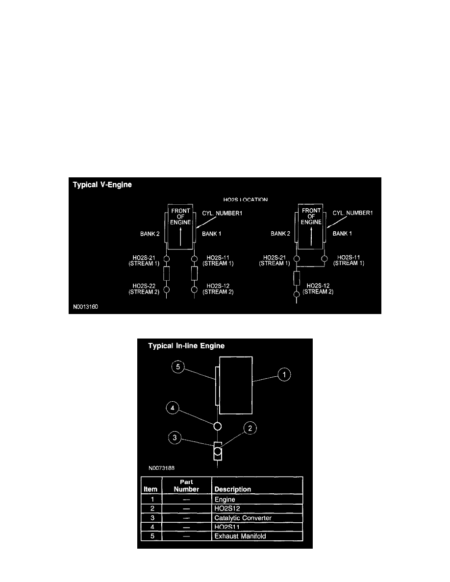
Only two HO2Ss are used in an exhaust stream. The front sensors (HO2S11/HO2S21) before the catalyst are used for primary fuel control while the
sensors after the catalyst (HO2S12/HO2S22) are used to monitor catalyst efficiency.
Typical V-Engine