
Grand Marquis V8-4.6L Flex Fuel (2010)
auxiliary batteries and power supplies (if equipped).
Failure to follow these instructions may result in serious personal injury or death in the event of an accidental deployment.
Disconnect the battery ground cable and wait at least one minute. For additional information, refer to Battery.
7. NOTE: A tool that has a blunt end, such as a 4.0 mm (0.15 in) Allen wrench, is better able to disengage the steering wheel spring clip from the
driver air bag module locking pins.
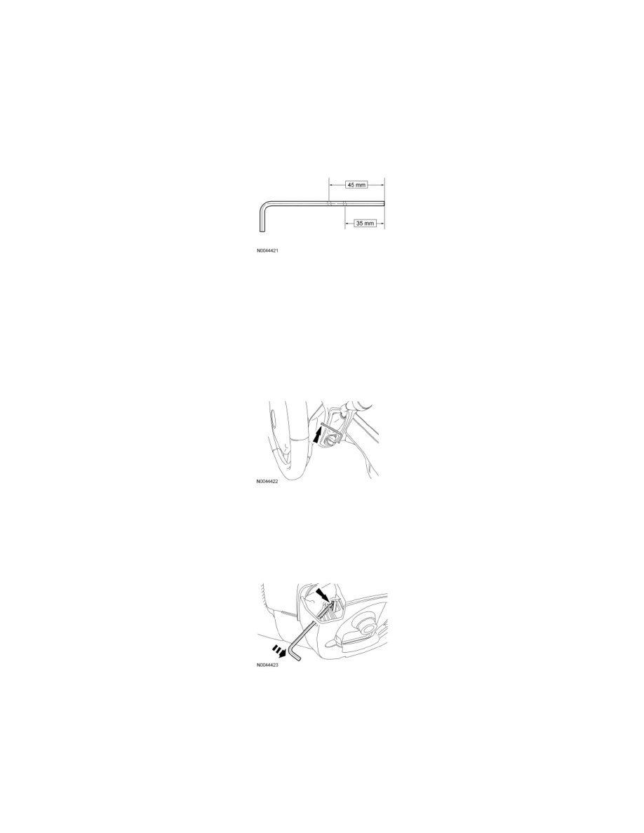
Using a 4 mm (0.15 in) Allen wrench or suitable tool, place 2 marks on the tool as an aid to remove the driver air bag module. One mark should be
approximately 35 mm (1.37 in) from the end of the tool with the second mark approximately 45 mm (1.77 in) from the end of the tool.
8. NOTE: The steering wheel rear cover has internal guides that assist in directing the tool to the correct location. Allow the steering wheel rear
cover to guide the tool, minimal force is needed.
Gently insert the tool into a steering wheel rear cover upper access hole until the end of the tool comes into contact with an obstruction. The 45
mm (1.77 in) mark on the tool should be even or close to even with the steering wheel rear cover. If the 45 mm (1.77 in) mark on the tool is not
even or close to even with the steering wheel rear cover, remove the tool from the steering wheel and carry out the step once again to correctly
position the tool.
-
If the 45 mm (1.77 in) mark on the tool goes into the steering wheel rear cover, the tool was directed past the steering wheel spring clip. Use a
tool of a slightly larger diameter or, using the internal guides of the steering wheel rear cover, insert the tool to the 45 mm (1.77 in) mark and
proceed to the next step.
9. NOTE: The steering wheel is removed for clarity. The upper corner of the steering wheel rear cover is cut away to show the internal guides and
the steering wheel spring clip.
With the tool correctly positioned, remove the tool approximately 2-3 mm (0.07-0.11 in) from the access hole then gently push the tool forward
(toward front of vehicle). This puts the tool in the best position to disengage the steering wheel spring clip from the driver air bag module locking
pin.
10. NOTE: Make sure to disengage the steering wheel spring clip from the driver air bag module locking pin before gently pulling the corresponding
corner of the driver air bag module. No or very little force is needed to separate the corresponding corner of the driver air bag module from the
steering wheel once the spring clip is disengaged from the locking pin.
NOTE: When the steering wheel spring clip is disengaged from the first locking pin, the corresponding corner of the driver air bag module will
only separate 2-4 mm (0.07-0.15 in) from the steering wheel. The driver air bag module will separate more noticeably as subsequent locking pins
are disengaged.
Push the tool deeper into the access hole (approximately 4-8 mm [0.15-0.31 in]) with enough force to disengage the steering wheel spring clip
from the driver air bag module locking pin. The corresponding corner of the driver air bag module should pop up once the spring clip is