
Grand Marquis V8-4.6L Flex Fuel (2010)
disengaged from the locking pin. Gently pull the corresponding corner of the driver air bag module to make sure the locking pin does not
reengage the spring clip. Remove the tool from the access hole. Discontinue pulling on the corresponding corner of the driver air bag module.
-
If the corresponding corner of the driver air bag module does not easily separate from the steering wheel, the spring clip is not disengaged
from the locking pin. Repeat the necessary steps to correctly position the tool and disengage the spring clip from the locking pin.
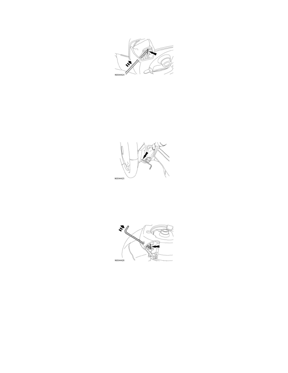
11. NOTE: The steering wheel rear cover has internal guides that assist in directing the tool to the correct location. Allow the steering wheel rear
cover to guide the tool, minimal force is needed.
Working on the same side of the steering wheel, gently insert the tool into a steering wheel rear cover lower access hole until the end of the tool
comes into contact with an obstruction. The 35 mm (1.37 in) mark on the tool should be even or close to even with the steering wheel cover. If the
35 mm (1.37 in) mark on the tool is not even or close to even with the steering wheel cover, remove the tool from the access hole and carry out the
step once again to correctly position the tool.
-
If the 35 mm (1.37 in) mark on the tool goes into the steering wheel rear cover, the tool was directed past the steering wheel spring clip. Use a
tool of a slightly larger diameter or, using the internal guides of the steering wheel rear cover, insert the tool to the 35 mm (1.37 in) mark and
proceed to the next step.
12. NOTE: The steering wheel is removed for clarity. The lower corner of the steering wheel rear cover is cut away to show the internal guides and
the steering wheel spring clip.
With the tool correctly positioned, remove the tool approximately 2-3 mm (0.07-0.11 in) from the access hole then gently push the tool forward
(toward front of vehicle). This puts the tool in the best position to disengage the steering wheel spring clip from the driver air bag module locking
pin.
13. NOTE: Make sure to disengage the steering wheel spring clip from the driver air bag module locking pin before gently pulling the corresponding
corner of the driver air bag module. No or very little force is needed to separate the corresponding corner of the driver air bag module from the
steering wheel once the spring clip is disengaged from the locking pin.
Push the tool deeper into the access hole (approximately 3-6 mm [0.11-0.23 in]) with enough force to disengage the steering wheel spring clip
from the driver air bag module locking pin. The corresponding corner of the driver air bag module should pop up once the spring clip is
disengaged from the locking pin. Gently pull the corresponding corner of the driver air bag module to make sure the locking pin does not
reengage the spring clip. Remove the tool from the access hole. Discontinue pulling on the corresponding corner of the driver air bag module.
-
If the corresponding corner of the driver air bag module does not easily separate from the steering wheel the spring clip is not disengaged from
the locking pin. Repeat the necessary steps to correctly position the tool and disengage the spring clip from the locking pin.