
Grand Marquis V8-4.6L Flex Fuel (2010)
CONNECT all modules. CONNECT the negative battery cable. GO to K23.
No
GO to K19.
-------------------------------------------------
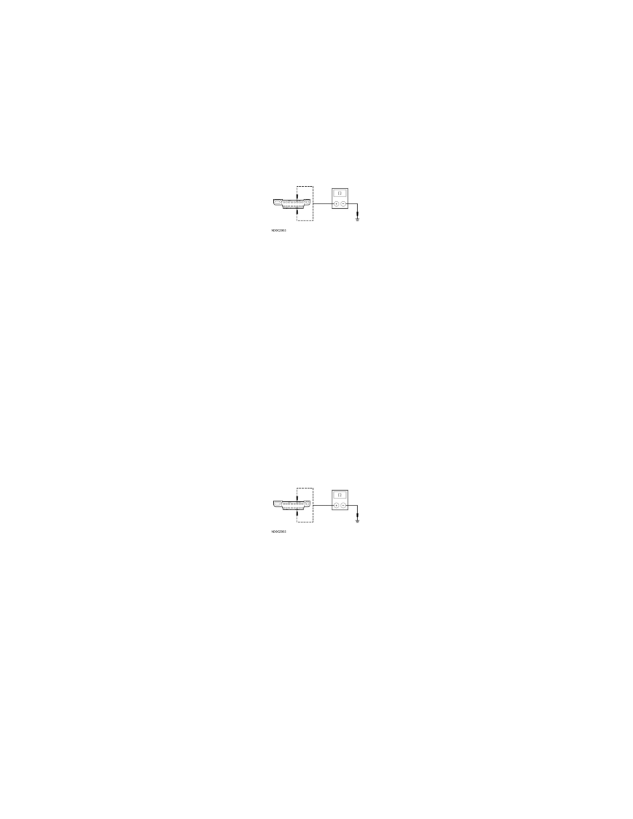
K19 CHECK THE HS-CAN (+) AND HS-CAN (-) CIRCUITS FOR A SHORT TO GROUND WITH THE IC DISCONNECTED
-
Disconnect: Instrument Cluster (IC) C2220.
-
Measure the resistance between the DLC C251-6, circuit 1827 (WH/LG), harness side and ground; and between the DLC C251-14, circuit 1828
(PK/LG), harness side and ground.
-
Are the resistances greater than 1,000 ohms?
Yes
CONNECT all modules. CONNECT the negative battery cable. GO to K24.
No
If the vehicle is equipped with a VDM, GO to K20.
If the vehicle is not equipped with a VDM, REPAIR the circuit in question. CONNECT all modules. CONNECT the negative battery cable. CLEAR the
DTCs. REPEAT the network test with the scan tool.
-------------------------------------------------
K20 CHECK THE HS-CAN (+) AND HS-CAN (-) CIRCUITS FOR A SHORT TO GROUND WITH THE VDM DISCONNECTED
-
Disconnect: VDM C2131a.
-
Measure the resistance between the DLC C251-6, circuit 1827 (WH/LG), harness side and ground; and between the DLC C251-14, circuit 1828
(PK/LG), harness side and ground.
-
Are the resistances greater than 1,000 ohms?
Yes
CONNECT all modules. CONNECT the negative battery cable. GO to K25.
No
REPAIR the circuit in question. CONNECT all modules. CONNECT the negative battery cable. CLEAR the DTCs. REPEAT the network test with the
scan tool.
-------------------------------------------------
K21 CHECK FOR CORRECT PCM OPERATION
-
Disconnect all the PCM connectors.
-
Check for:
-
corrosion
-
damaged pins
-
pushed-out pins
-
Connect all the PCM connectors and make sure they seat correctly.
-
Operate the system and verify the concern is still present.