
Grand Marquis V8-4.6L Flex Fuel (2010)
-
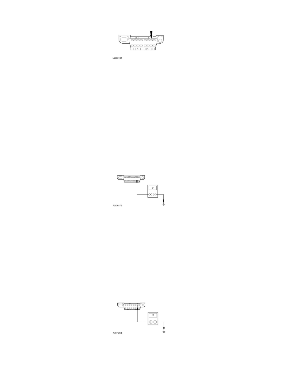
Inspect the DLC pin 7 for damage.
-
Is the DLC pin 7 OK?
Yes
GO to L2.
No
REPAIR the DLC as necessary. CLEAR the DTCs. REPEAT the network test with the scan tool.
-------------------------------------------------
L2 CHECK THE ISO 9141 CIRCUIT FOR A SHORT TO VOLTAGE
-
Disconnect: Negative Battery Cable.
-
Wait at least 1 minute.
-
Disconnect: RCM C310a.
-
Disconnect: FSSM C3281a (If Equipped).
-
Ignition ON.
-
Measure the voltage between the DLC C251-7, circuit 70 (LB/WH), harness side and ground.
-
Is any voltage present?
Yes
REPAIR the circuit. CONNECT all modules. CONNECT the negative battery cable. CLEAR the DTCs. REPEAT the network test with the scan tool.
No
GO to L3.
-------------------------------------------------
L3 CHECK THE ISO 9141 CIRCUIT FOR A SHORT TO GROUND
-
Ignition OFF.
-
Measure the resistance between the DLC C251-7, circuit 70 (LB/WH), harness side and ground.
-
Is the resistance greater than 10,000 ohms?