
Grand Marquis V8-4.6L Flex Fuel (2010)
1. Connect the rear window defrost switch electrical connector.
2. If equipped, connect the clock electrical connector.
3. Connect the PAD indicator.
4. Align the retaining clips, slide the trim panel to the left and push in, seating the retaining clips.
15. Connect the glove compartment isolator.
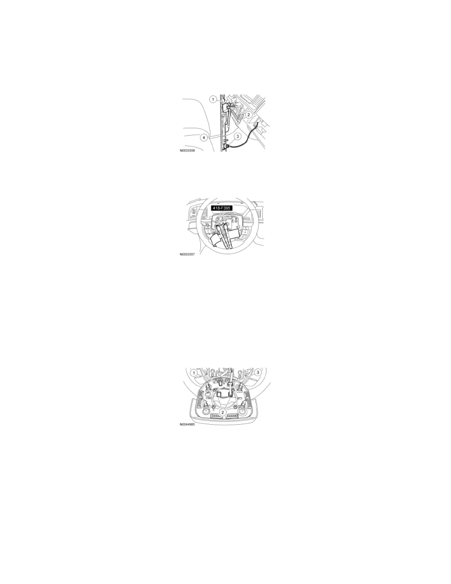
16. Remove the Restraint System Diagnostic Tool from each of the clockspring electrical connectors at the top of the steering column.
17. Connect the driver air bag module.
1. Connect the horn electrical connector.
2. NOTICE: The clockspring electrical connectors are unique and cannot be reversed when connected to the driver air bag module.
Match the electrical connector key to the keyway in the driver air bag module. Do not force the electrical connectors into the driver
air bag module. Damage to the connector or component may occur.
Connect the driver air bag module electrical connectors as noted during removal.
3. Install the driver air bag module electrical wiring into the driver air bag wiring clip.
18. NOTE: With the driver air bag module held as close to the steering wheel as possible, take up the slack in the wiring by gently tucking any excess
length into the pocket at the bottom of the steering wheel before rocking the driver air bag module into place.
Align the 4 driver air bag module locking pins to the openings in the steering wheel and position the driver air bag module in place.