
Grand Marquis V8-4.6L VIN V Flex Fuel (2006)
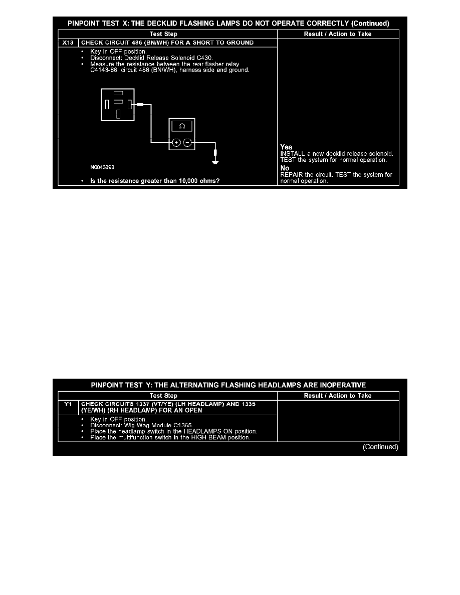
X13
Normal Operation
The rear flasher relay is supplied voltage from the battery junction box (BJB) through circuit 1271 (VT). Voltage is provided through circuit 705
(LG/OG) to the rear flasher relay coil. Ground for the rear flasher relay coil is provided through circuit 486 (BN/WH) to the decklid ajar switch when
the decklid is open. When the relay is energized, voltage is routed through circuit 383 (RD/WH) to the rear flasher. The rear flasher in turn, alternates
voltage to the LH and RH flasher lamps through circuits 1 (DB) and 2 (WH/LB), respectively.
Possible Causes
-
Fuse
-
Circuit 1 (DB) open, short to ground or voltage
-
Circuit 2 (WH/LB) open, short to ground or voltage
-
Circuit 383 (RD/WH) open or short to voltage
-
Circuit 486 (BN/WH) open or short to ground
-
Circuit 705 (LG/OG) open
-
Circuit 1271 (VT) open
-
Rear flasher
-
Rear flasher relay
Test Y: The Alternating Flashing Headlamps Are Inoperative
PINPOINT TEST Y: THE ALTERNATING FLASHING HEADLAMPS ARE INOPERATIVE
Y1