
Grand Marquis V8-4.6L VIN V Flex Fuel (2006)
-
If equipped with fire suppression system, depower the system. For important safety warnings and procedures refer to Fire Suppression System.
-
The electrical power to the air suspension system must be turned off prior to hoisting, jacking or towing an air suspension vehicle. Failure to
do so can result in unexpected inflation or deflation of the air springs, which can result in shifting of the vehicle during these operations.
Failure to follow these instructions may result in personal injury.
Remove the LH and RH front wheel and tire assemblies.
7. CAUTION: Do not allow the intermediate shaft to rotate while it is disconnected from the steering gear or damage to the clockspring can
result. If there is evidence that the intermediate shaft has rotated, the clockspring must be removed and recentered
Remove the bolt and detach the intermediate shaft from the steering gear.
8. Remove the 2 nuts and the 2 bolts from the LH number 2 crossmember bracket and the 2 nuts and the 2 bolts from the RH number 2 crossmember
bracket.
-
Separate the number 2 crossmember brackets from the crossmember.
9. Raise and support the vehicle.
10. Remove the 2 engine mount nuts.
11. NOTE: The hex holding feature can be used to prevent turning of the stud while removing the nut.
Remove the 2 nuts and disconnect the LH and RH stabilizer bar links.
12. NOTE: The hex holding feature can be used to prevent turning of the stud while removing the nut.
Remove the 2 nuts and disconnect the LH and RH outer tie-rod ends.
13. Remove the 2 bolts and position the LH and RH brake hose and brackets assemblies aside.
14. Remove the 4 bolts and position the LH and RH brake calipers aside.
-
Support the brake calipers away from the number 2 crossmember.
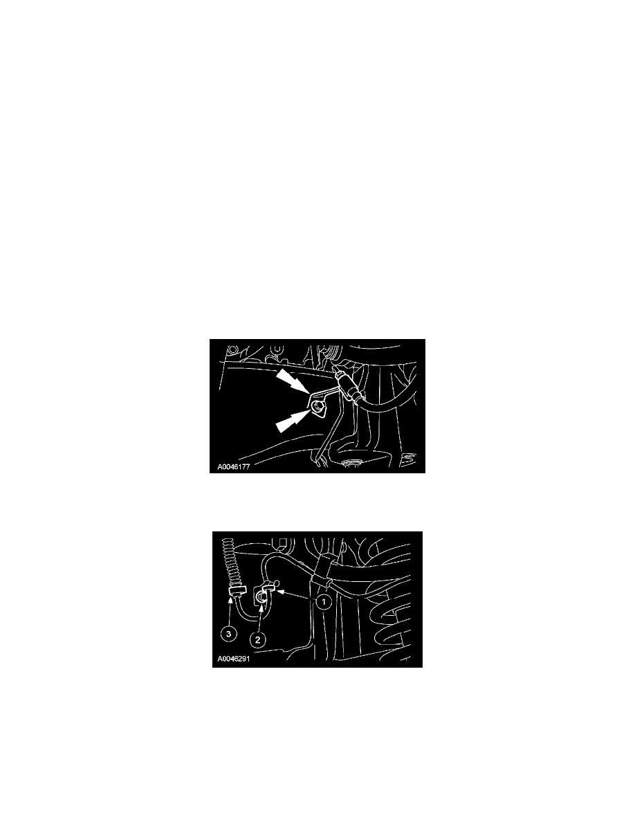
15. Position the front LH and RH ABS harness aside.
1. Release the 2 ABS harnesses from the support bracket.
2. Remove the 2 bolts and the brackets.
3. Remove the 2 harness retainers from the frame.
16. Remove the 2 steering gear nuts.