
Grand Marquis V8-4.6L VIN V Flex Fuel (2006)
The warning messages that reoccur after 10 minutes are:
-
COOLANT OVER TEMPERATURE
-
POWERTRAIN MALFUNCTION
-
CHECK FUEL CAP
-
LOW FUEL
-
CHECK AIR SUSPENSION
The warning messages that display whenever the ignition switch is turned from the OFF position to the ON position are:
-
OVERDRIVE ON/OFF
-
TRUNK AJAR
-
CHECK COMPASS MODULE
-
LOW WASHER FLUID
-
CHANGE ENGINE OIL
Inspection and Verification
INSPECTION AND VERIFICATION
WARNING: If equipped with the fire suppression system, refer to Fire Suppression System for important safety warnings.
1. Verify the customer concern.
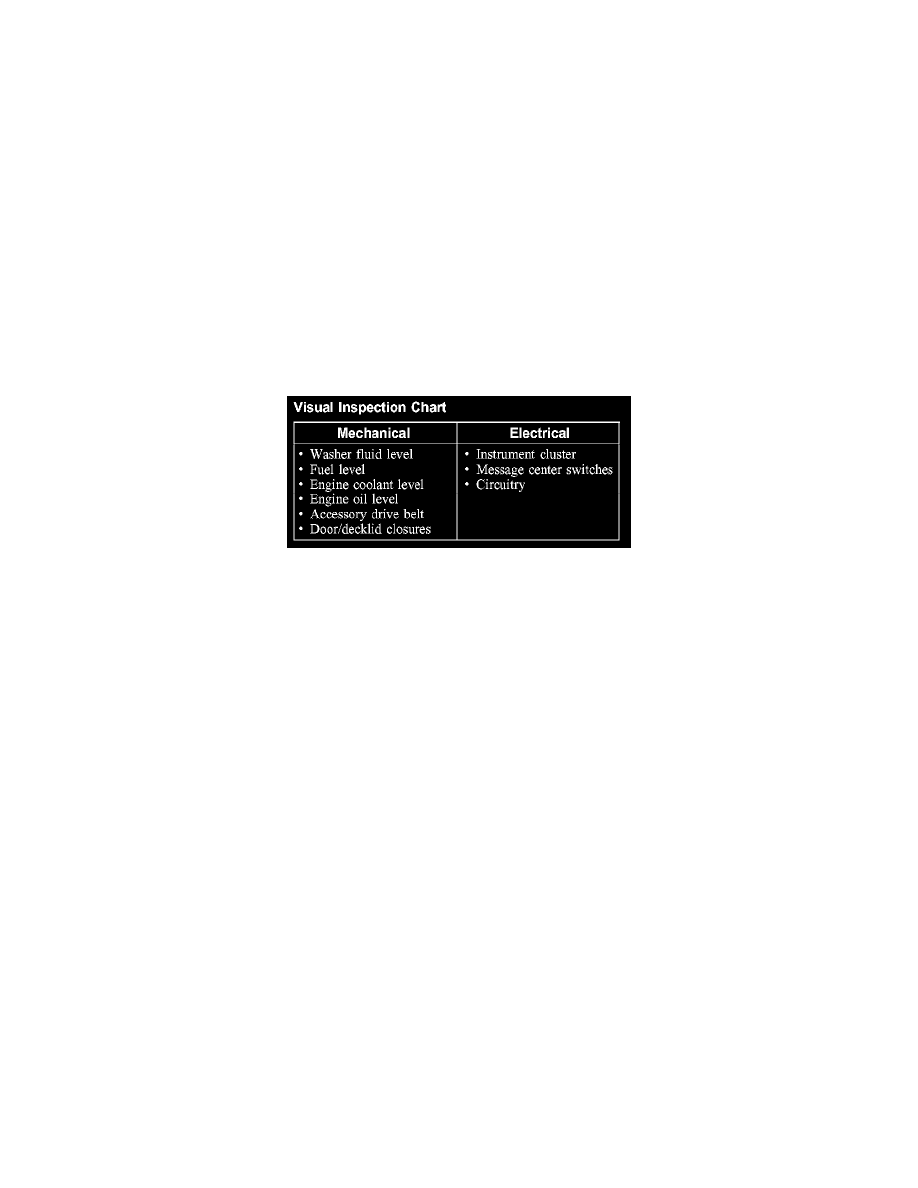
Visual Inspection Chart
2. Visually inspect for obvious signs of mechanical or electrical damage.
3. If an obvious cause for an observed or reported concern is found, correct the cause (if possible) before proceeding to the next step.
4. If the cause is not visually evident, connect the diagnostic tool to the data link connector (DLC) and select the vehicle to be tested from the
diagnostic tool menu. If the diagnostic tool does not communicate with the vehicle:
-
check that the program card is correctly installed.
-
check the connections to the vehicle.
-
check the ignition switch position.
5. If the diagnostic tool still does not communicate with the vehicle, refer to the diagnostic tool operating manual.
6. Carry out the diagnostic tool data link test. If the diagnostic tool responds with:
-
SCP or CAN circuit fault; all electronic control units no response/not equipped, refer to Information Bus (Module Communications Network).
-
No response/not equipped for the instrument cluster, refer to Instrument Cluster.
-
No response/not equipped for the lighting control module (LCM), refer to Body Control Systems (Multifunction Electronic Control Module).
-
System passed, retrieve and record the continuous diagnostic trouble codes (DTCs), erase the continuous DTCs, and carry out self-test
diagnostics for the instrument cluster.
7. If the DTCs retrieved are related to the concern, refer to the Instrument Cluster Diagnostic Trouble Code (DTC) Index or the Lighting Control
Module (LCM) DTC Index. See: Diagnostic Trouble Code Descriptions/Instrument Cluster Diagnostic Trouble Code (DTC) Index See:
Diagnostic Trouble Code Descriptions/Lighting Control Module (LCM) Diagnostic Trouble Code (DTC) Index
8. If no DTCs related to the concern are retrieved, GO to Symptom Chart. See: Symptom Related Diagnostic Procedures