
Grand Marquis V8-4.6L VIN V Flex Fuel (2006)
^
A vibration during coastdown from 72 to 56 km/h (45 to 35 mph) is often caused by an excessive U-joint angle at the axle (pinion nose
downward).
^
A vibration during acceleration, from 56 to 72 km/h (35 to 45 mph) may indicate an excessive U-Joint angle at the axle (pinion nose upward).
When these conditions exist, check the driveline angles.
If the tires and driveline angle are not the cause, carry out the NVH tests to determine whether the concern is caused by a condition in the axle. Refer
to Vehicle/Testing and Inspection.
Universal Joint (U-Joint) Wear
WARNING: The electrical power to the air suspension system must be shut off prior to hoisting, jacking or towing an air suspension vehicle.
This can be accomplished by turning off the air suspension switch. Failure to do so can result in unexpected inflation or deflation of the air
springs, which can result in shifting of the vehicle during these operations.
Place the vehicle on a frame hoist and rotate the driveshaft by hand. Check for rough operation or seized U-joints. Install a new U-joint if it shows
signs of seizure, excessive wear or incorrect seating.
Wheel Hub or Axle Flange Bolt Circle Runout
NOTE: The brake discs must be removed to carry out all runout measurements.
1. Position the Dial Indicator Gauge with Holding Fixture perpendicular to the wheel hub or axle flange bolt, as close to the hub or flange face as
possible. Zero the indicator to allow the pointer to deflect either way.
2. Rotate the hub or flange until the next bolt is contacted. Record the measurement and continue until each bolt is checked. The difference between
the maximum and minimum contact readings will be the total wheel hub or axle flange bolt pattern runout. The runout must not exceed 0.38 mm
(0.015 inch).
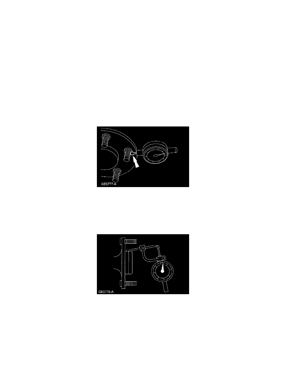
Pilot Runout
1. Position the Dial Indicator Gauge with Holding Fixture with the Clutch Housing Gauge to the pilot, as close to the hub or axle flange face as
possible. Zero the indicator to allow the pointer to deflect either way.
2. Rotate the hub or flange one full turn and note the maximum and minimum readings. The difference between the maximum and minimum readings
will be the total pilot runout. Pilot runout must not exceed 0.15 mm (0.006 inch).
Wheel Hub or Axle Flange Face Runout
NOTE: If the axle shaft assembly is removed, check runout of the shaft itself. The forged (unmachined) part of the shaft is allowed to have as much
as 3.0 mm (0.120 inch) runout. This alone will not cause a vibration condition.