
Grand Marquis V8-4.6L VIN V Flex Fuel (2006)
2. NOTE: Manual shift lever shaft must be in the neutral position.
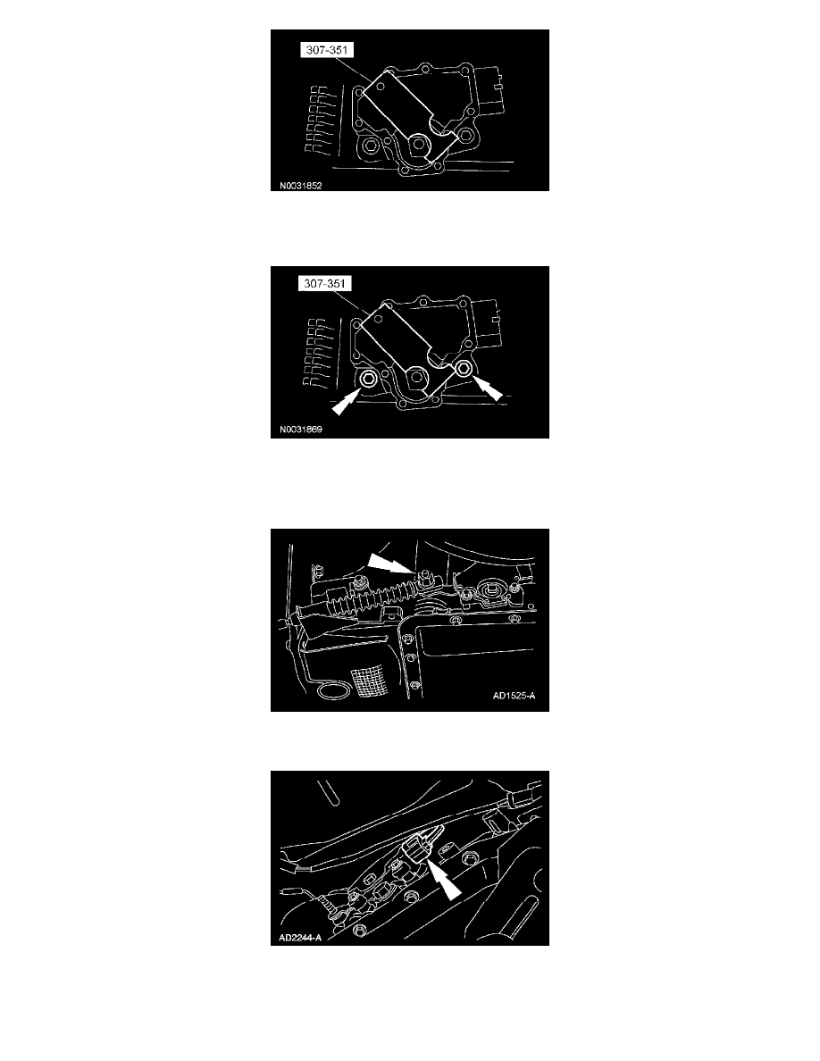
Using the special tool, align the digital TR sensor slots. The tool is designed to fit snugly.
3. CAUTION: Tightening one screw before tightening the other may cause the sensor to bind or become damaged.
Tighten the screws in an alternating sequence.
^
Tighten to 9 Nm (80 inch lbs.).
4. With the manual lever in overdrive, connect the shift lever control cable.
^
Tighten to 23 Nm (17 ft. lbs.).
5. Connect the digital TR sensor electrical connector.
6. WARNING: If equipped with fire suppression system, repower the system. For important safety warnings and procedures, refer to Fire
Suppression System.