
LN7 L4-098 1.6L VIN 4 2-bbl (1982)
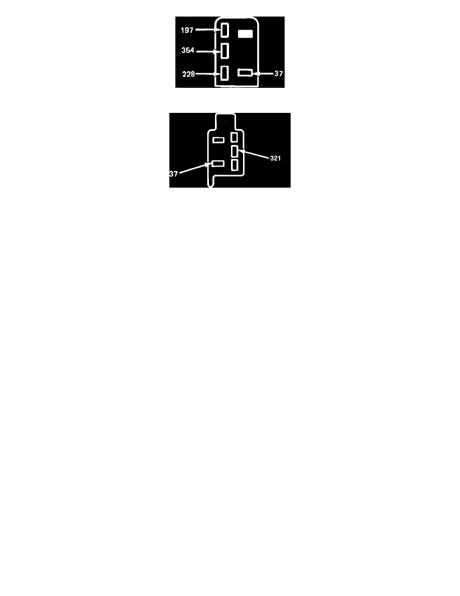
Fig. 6 Cooling fan relay wire connector terminal identification. Exc. type 4
Fig. 7 A/C relay wire connector terminal identification
Refer to Fig. 4, during the following procedures.
1.
Check cooling fan fusible link. If fusible link is not blown, go to step 2. If blown, repair and retest.
2.
Disconnect coolant temperature switch connector, then connect a jumper wire from connector to ground and turn ignition ``On.'' If fan motor does
not run, proceed to step 3. If fan motor does run, primary system is operating satisfactory. If complaint is overheating, replace coolant temperature
switch.
3.
Connect coolant temperature switch connector. Set A/C controls on maximum and turn ignition ``On.'' If fan motor does not run, proceed to step 4.
If fan motor runs, system is satisfactory.
4.
Disconnect fan motor electrical connector, then connect a jumper wire from motor ground connection to a known good ground and a jumper wire
from battery positive to motor B+ connection, Fig. 5. If motor does not run, replace motor. If motor runs, reconnect electrical connection and
proceed to step 5.
5.
Disconnect cooling fan relay connector and turn ignition ``On.'' Using a test light, check for voltage at terminals 37 and 354, Fig. 6. If there is no
voltage at one or both terminals, service relay feed circuits. If voltage at both terminals, proceed to step 6.
6.
Connect jumper wire between terminals 354 and 228, Fig. 6. If fan motor does not run, repair wiring from relay connector to motor connector. If
motor runs, disconnect jumper wire and proceed to step 7.
7.
Using an ohmmeter, check continuity of wire 228 from relay connector to coolant temperature switch connector. If no continuity exists, repair
wires and/or connectors. If continuity exists, replace cooling fan relay and recheck step 2.
8.
Disconnect A/C relay connector. Using an ohmmeter, check continuity of wire 228 from relay to motor. If no continuity exists, repair wires and/or
connectors. If continuity exists, proceed to step 9.
9.
Reconnect fan motor connector, then disconnect A/C relay connector. Set A/C controls on maximum and turn ignition ``On.'' Using a test light,
check for voltage at terminals 37 and 321, Fig. 7. If there is no voltage at one or both terminals, service relay feed circuits or A/C control and
recheck step 3. If there is voltage at both terminals, go to step 10.
10.
Connect jumper wire to base of relay and connect to known good ground. If fan motor does not run, replace relay and recheck step 3. If fan motor
runs, clean relay ground.