
LN7 L4-098 1.6L VIN 4 2-bbl (1982)
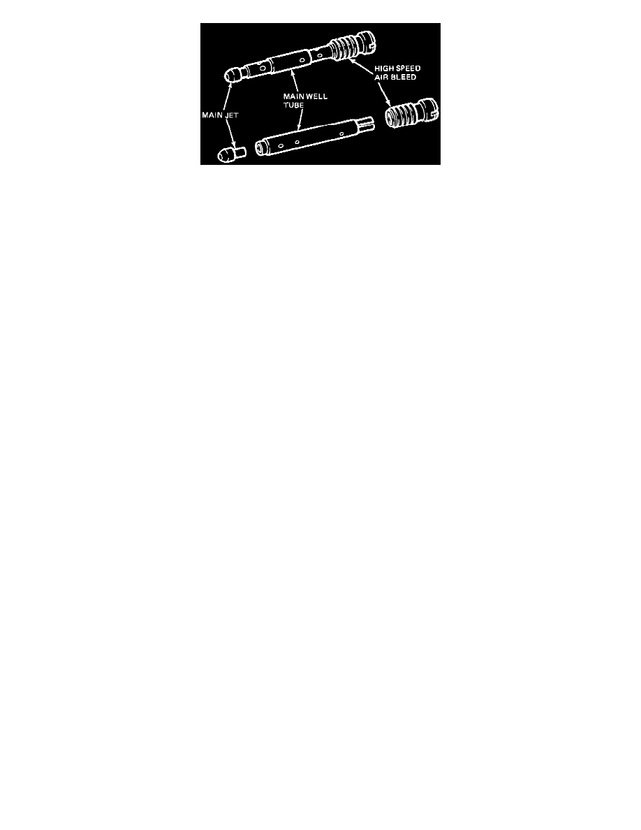
Figure 3
6.
The high speed air bleed, main well tube and main jet are press fit assemblies and can be taken apart by hand (Figure 3).
7.
Replace the primary high speed air bleed identified by the number 175 stamped on air bleed with the new air bleed stamped 200 (contained in Kit
No. E2PZ-9D544-J).
8.
Apply one drop of Ford Spec ESE-M4G-204-A3 (Loctite 262 or equivalent) on the threads of the MMJ assembly. Install and torque to 2.0 Newton
meters or 17 in.-lbs.
NOTE:
If difficulty is incurred with installing MMJ assemblies, refer to TSB 82-4 for alternative installation procedure.
9.
Unscrew the secondary high speed air bleed, main well tube and main jet assembly (Figure 2).
10.
Using a thin needle nose pliers, carefully lift the assembly out of the carburetor.
11.
Replace the secondary high speed air bleed identified by the number 150 stamped on air bleed, with the new air bleed stamped 200 (contained in
Kit No. E2PZ-9D544-J).
12.
Apply one drop of Ford Spec ESE-M4G-204-A3 (Loctite 262 or equivalent) on the threads of each MMJ assembly. Install and torque to 2.0
Newton meters or 17 in.lbs.
13.
Install air cleaner bail and retaining pin.
14.
Check and reset, if necessary, all idle speeds as per 1982 Car/Truck Shop Manual Engine/Emission Diagnosis Book I, Section 4, 4-15 thru 18,
Carburetor Systems.
15.
Install the air cleaner assembly.
16.
Install a Ford Modification Decal adjacent to the Emission Control Information Decal listing high speed air bleed changes.
All Automatic Transmissions
1.
Remove air cleaner assembly and set aside.
2.
Remove the air cleaner bail retaining pin by using a pliers with a firm grip, to disengage light pin press.
3.
Remove air cleaner bail.
4.
Unscrew the primary and high speed air bleed, main well tube and main jet assembly (Figure 2).
NOTE:
The MMJ assemblies are staked in production. A moderate amount of resistance may be incurred when removing the MMJ assemblies. In
addition, care should be taken in order to prevent any chips from entering the main well.
5.
Using a thin needle nose pliers, carefully lift the assembly out of the carburetor.
6.
The high speed air bleed, main well tube and main jet are press fit assemblies and can be taken apart by hand (Figure 3).
7.
Replace the primary high speed air bleed identified by the number 175 stamped on air bleed with the new air bleed stamped 190 (contained in Kit
No. E2PZ-9D544-K).
8.
Apply one drop of Ford Spec ESE-M4G-204-A3 (Loctite 262 or equivalent) on the threads of the MMJ assembly. Install arid torque to 2.0
Newton meters or 17 in.lbs.
NOTE:
If difficulty is incurred with installing MMJ assemblies, refer to TSB 82-4 for alternative installation procedure.
9.
Unscrew secondary high speed air bleed. main well tube and main jet assembly (Figure 2).
10.
Using a thin needle nose pliers, carefully lift the assembly out of the carburetor.
11.
Replace the secondary high speed air bleed identified by the number 150 stamped on air bleed with the new air bleed stamped 1 95 (contained in
Kit No. E2PZ-9D544-K).
12.
Apply one drop of Ford Spec ESE-M4G-204-A3 (Loctite 262 or equivalent) on the threads of each MMJ assembly. Install and torque to 2.0
Newton meters or 17 in.lbs.
13.
Install air cleaner bail and retaining pin.
14.
Check and reset, if necessary, all idle speeds as per 1981 Car/Truck Shop Manual - Engine/Emission Diagnosis Book I, Section 4, 4-15 thru 18,
Carburetor Systems.