
Lynx L4-116 1.9L VIN J FI HP (1986)
Control Module HVAC: Testing and Inspection
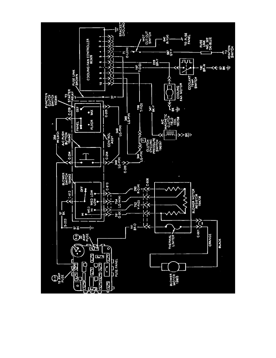
Fig. 36 Electric engine cooling fan wiring diagram. Type 30
Refer to Fig. 36, during the following procedures.
1.
Check fuse and fusible link. If satisfactory, proceed to step 2. If not satisfactory, repair or replace as necessary.
2.
Bring engine to operating temperature while operating A/C to determine when cooling fan does or does not operate. If cooling fan operates only
during A/C operation, proceed to step 3. If cooling fan does not operate during A/C operation or during high engine coolant temperatures, proceed
to step 12. If cooling fan only operates during high engine coolant temperature, proceed to step 7.
3.
Disconnect coolant temperature switch electrical connector, then connect a jumper wire from connector to ground. If fan motor operates, proceed
to step 4. If fan motor does not operate, proceed to step 5.