
Mariner 2WD L4-2.3L VIN H Hybrid (2006)
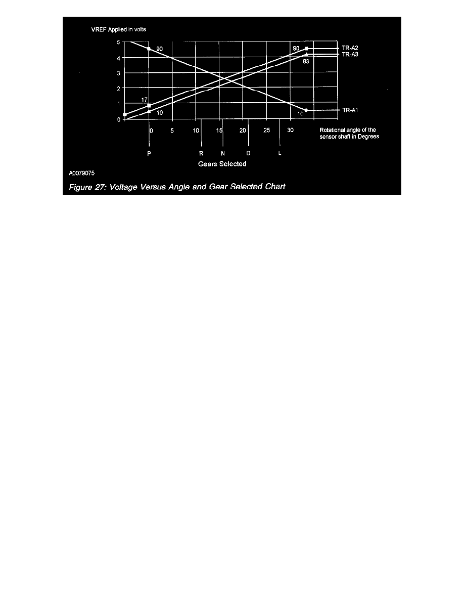
Voltage Versus Angle And Gear Selected Chart
Overview
The TR sensor communicates the gear selector position that the driver selects to the PCM. The PCM determines a gear mode based on the TR input
and the vehicle speed signal. The PCM then broadcasts a gear mode message over the communication link. The transmission control module (TCM)
uses the gear mode message to engage the transaxle in the gear that the driver selected. The other control modules use the gear mode message to
control the rear lamps or a brake shift interlock solenoid. The TR sensor is mounted at the base of the gear selector assembly and the sensor shaft is
moved by the selector.
TR Sensor and PCM Interface
The TR sensor is a linear potentiometer device that provides the PCM with a percentage of input voltage proportional to the rotational angle of the
sensor shaft. The TR sensor consists of:
-
3 independent (TR-A1, TR-A2 and TR-A3) signals.
-
2 5 volt reference (TR-VREF1 and TR-VREF2) lines.
-
2 signal return (TR-RTN1 and TR-RTN2) lines.
The TR-A1 signal has a negative voltage slope, meaning the voltage decreases when the sensor angle increases. The typical TR voltage ranges from
approximately 4.5 volts in the PARK position to approximately 1 volt in the LOW gear position. The TR-A2 and the TR-A3 signals both have a
positive voltage slope. Voltages increase as the sensor angle increases. The typical voltage for the TR-A2 and the TR-A3 range from about 0.6 volts in
the PARK position to about 3.5 volts in the LOW gear position.
The TR-VREF circuits are bussed together internal to the TR sensor, and both TR-RTN circuits are bussed together in the TR sensor. One of the
TR-VREF and one of the TR-RTN circuits are dedicated signals from the PCM. This design of redundant signals protects against an open circuit
condition.
If the PCM detects a fault condition in one of TR signal inputs, it uses the other 2 TR signals to determine what gear the driver selects. If the PCM
detects 2 or more TR signals that are invalid, the PCM:
-
allows the vehicle to travel in DRIVE position or LOW gear position if the vehicle was driving forward at a significant speed when the fault was
detected.
-
allows the vehicle to travel in REVERSE gear if the vehicle was driving backwards at a significant speed when the fault was detected.
-
broadcasts gear mode - NEUTRAL over the communication link when vehicle speed decreases to 8 km/h (5 mph).
-
sets the diagnostic trouble code (DTC) and illuminates the indicator light.