
Mariner 2WD L4-2.5L Hybrid (2010)
10. NOTE: Measure the backlash and verify that it is within specified range at all of the following 6 positions: 10 degrees, 30 degrees, 100 degrees,
190 degrees, 210 degrees and 280 degrees. It will be necessary to reset the measuring equipment between measurements.
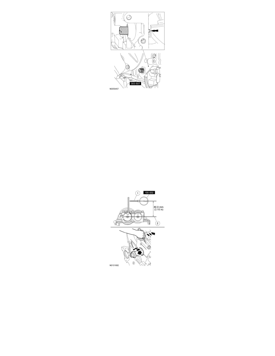
NOTE: The measurement must be taken with the Dial Indicator Gauge with Holding Fixture, a 5-mm Allen wrench and worm clamp set up as
shown. Mark the Allen wrench with a file 80 mm (3.149 in) above the driven gear shaft center. Make sure the worm clamp and Allen wrench are
not touching the balance shaft housing.
NOTE: For an accurate measurement while measuring the gear backlash, insert a screwdriver as shown into the crankshaft No. 1 crankweight area
and set both the rotation and the thrust direction with the screwdriver, using a prying action as shown.
Position the Dial Indicator Gauge with Holding Fixture as shown. Measure the gear backlash.
-
Position the Dial Indicator Gauge with Holding Fixture (1) on the Allen wrench 80 mm (3.149 in) above the driven gear shaft center (2) on the
balancer unit.
-
Rotate the crankshaft clockwise and measure the backlash at all of the following 6 positions: 10 degrees, 30 degrees, 100 degrees, 190 degrees,
210 degrees and 280 degrees.
11. NOTE: If maximum backlash exceeds 0.101 mm (0.003 in), install a new balancer unit.
Using the backlash measurement, select the proper shims from the Adjustment Shim Selection Table.
-
Remove the balancer unit from the cylinder block.
-
Install the selected adjustment shims on the seat faces of the balancer unit.