
Mariner 2WD L4-2.5L Hybrid (2010)
-
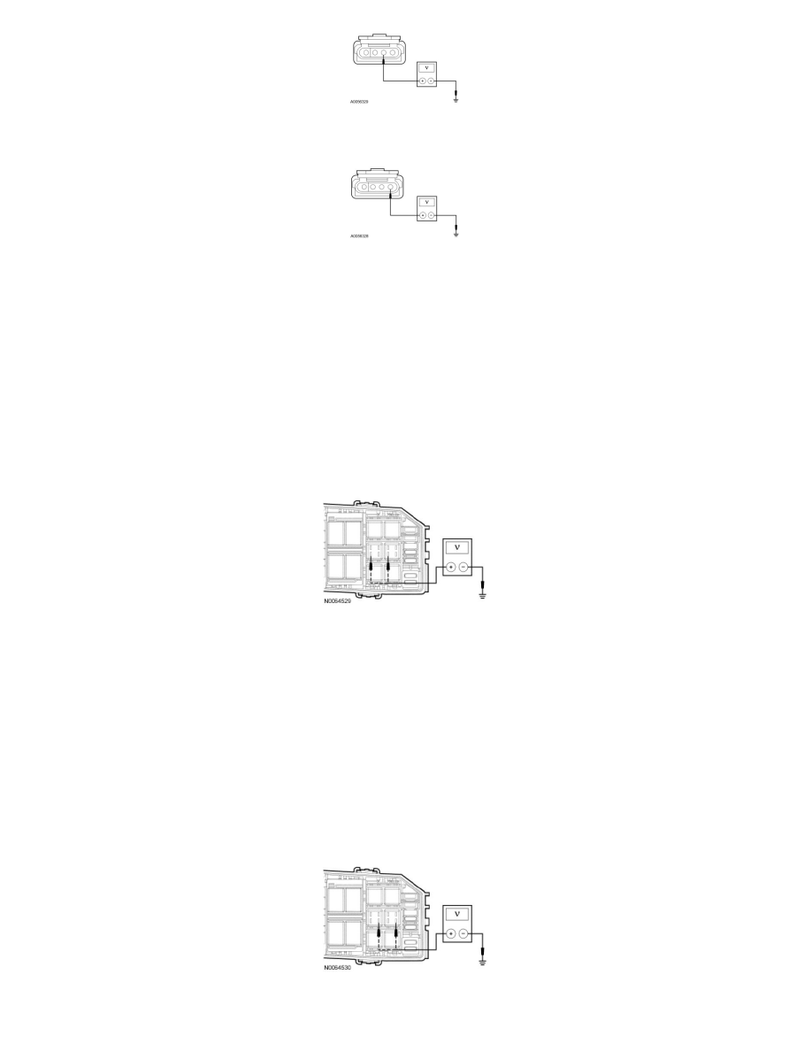
For the RH trailer stop/turn lamp, while applying the brake pedal, measure the voltage between the trailer tow C439-1, circuit CAT09 (GN),
harness side and ground.
-
Is the voltage greater than 10 volts?
Yes
REMOVE the known good relay. INSTALL a new trailer tow stop/turn relay. TEST the system for normal operation.
No
REMOVE the known good relay. GO to Z3.
-------------------------------------------------
Z3 CHECK FOR VOLTAGE TO THE TRAILER TOW STOP/TURN RELAY COIL
-
While applying the brake pedal, measure the voltage between the trailer tow LH stop/turn relay pin 2, circuit CLS18 (GY/BN), BJB face side and
ground; or between the trailer tow RH stop/turn relay pin 2, circuit CLS19 (VT/OG), BJB face side and ground.
-
Is the voltage greater than 10 volts?
Yes
GO to Z4.
No
REPAIR the circuit in question for an open. TEST the system for normal operation.
-------------------------------------------------
Z4 CHECK FOR VOLTAGE TO THE TRAILER TOW STOP/TURN RELAY
-
Measure the voltage between the trailer tow LH stop/turn relay pin 3, circuit SBB14 (BN/RD), BJB face side and ground; or between the trailer
tow RH stop/turn relay pin 3, circuit SBB14 (BN/RD), BJB face side and ground.
-
Is the voltage greater than 10 volts?