
Mariner 2WD L4-2.5L Hybrid (2010)
-
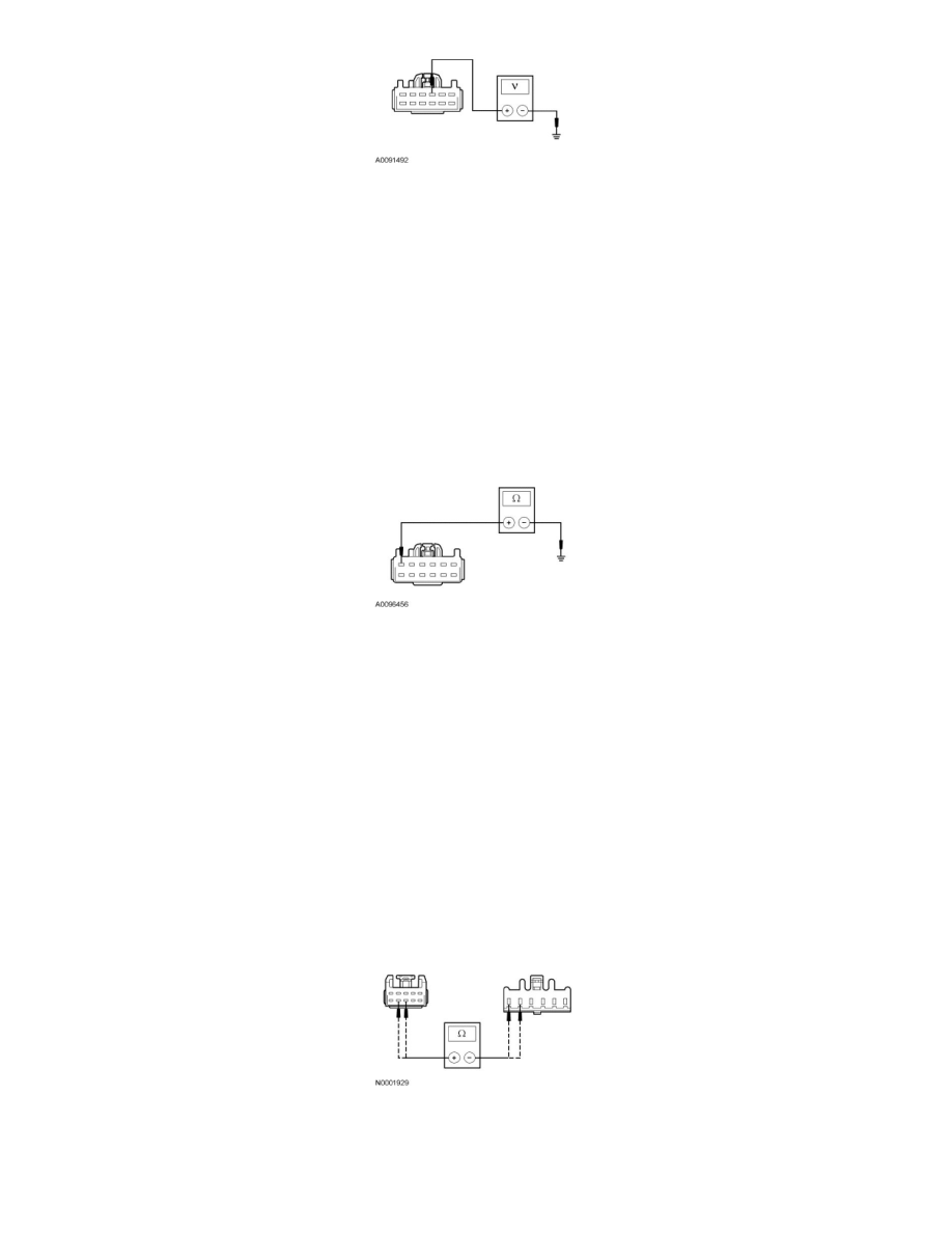
Is the voltage greater than 10 volts?
Yes
GO to B2.
No
CHECK the Smart Junction Box (SJB) fuse 35 (10A). If OK, REPAIR the circuit. If not OK, Refer to the Wiring Diagrams to locate the possible cause
of the circuit short. TEST the system for normal operation. See: Diagrams/Electrical Diagrams/Diagrams By Number
-------------------------------------------------
B2 CHECK THE GROUND CIRCUIT FOR AN OPEN
-
Ignition OFF.
-
Measure the resistance between DC/AC inverter C2293A-6, circuit GD182 (BK/GY), harness side and ground.
-
Is the resistance less than 5 ohms?
Yes
GO to B3.
No
REPAIR circuit GD182 (BK/GY). TEST the system for normal operation.
-------------------------------------------------
B3 CHECK THE LED CONTROL CIRCUITS FOR AN OPEN
-
Disconnect: DC/AC Inverter C2293B.
-
Disconnect: AC Power Point C2292.
-
Measure the resistance between DC/AC inverter C2293B-9, circuit LYA03 (YE/VT), harness side and AC power point C2292-6 circuit LYA03
(YE/VT), harness side; and between DC/AC inverter C2293B-8, circuit RYA03 (BU/BN), harness side and AC power point C2292-5 circuit
RYA03 (BU/BN), harness side.
-
Are the resistances less than 5 ohms?
Yes
GO to B4.