
Mariner 2WD L4-2.5L Hybrid (2010)
Installation
1. NOTE: If cleaning the main control assembly or inspecting the valves, refer to Main Control Valve Body See: Service and
Repair/Overhaul/Disassembly and Assembly of Subassemblies/Main Control Valve Body. If installing a new main control assembly, continue with
this procedure.
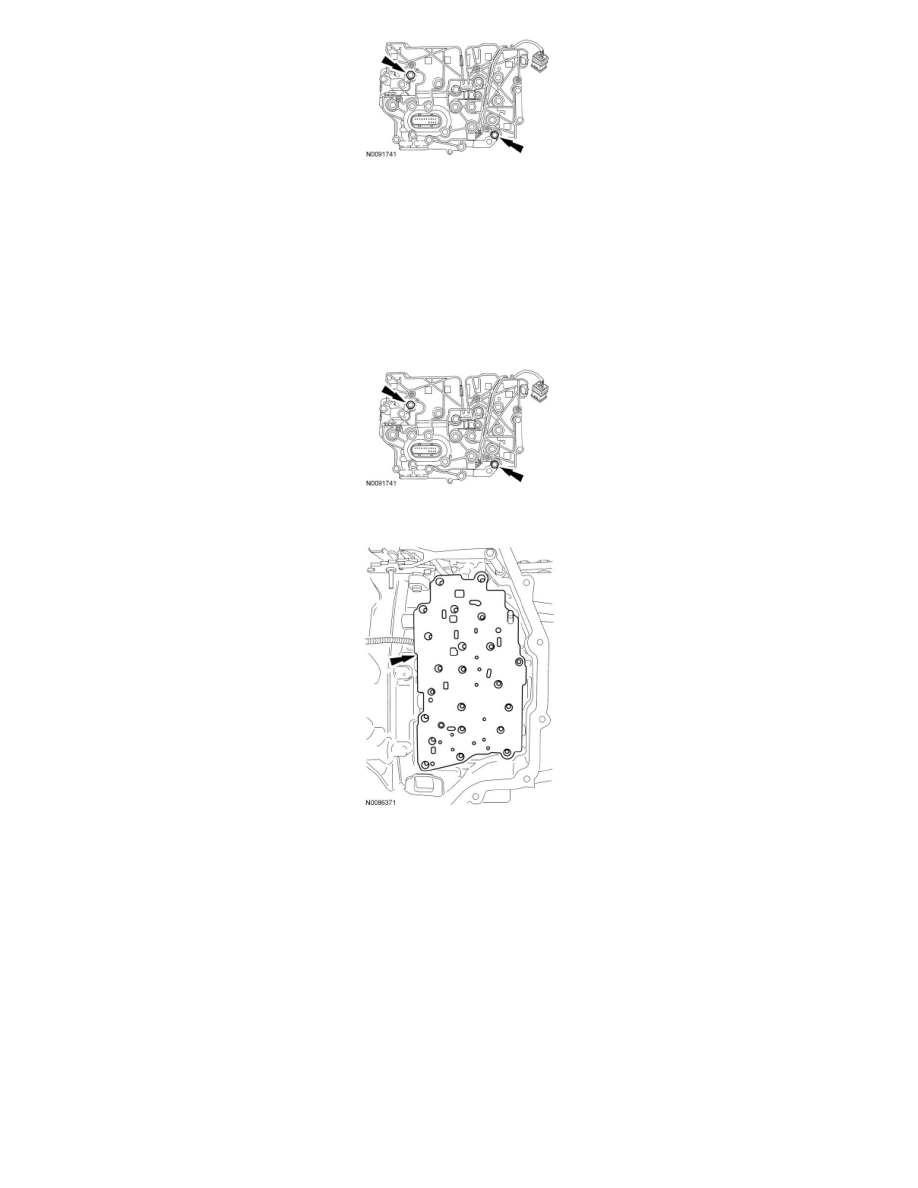
NOTE: Make sure that the manual lever pin (part of the TR sensor) is correctly installed in the manual valve.
Install the solenoid body assembly onto the main control valve body. Install the 2 bolts.
-
Tighten to 10 Nm (89 lb-in).
2. Position the OSS and TR sensor wiring harnesses aside and install the main control-to-transaxle case separator plate.
3. NOTE: Make sure that the manual lever pin (part of the TR sensor) is correctly installed in the manual valve.
Install the main control valve body.