Mariner 2WD V6-3.0L (2008)

Network Topology (Part 2)
ISO 9141 Network Operation
The ISO 9141 communications network is a single wire network, used for diagnostic purposes only.
The ISO 9141 communications network is used for the following module:
-
Parking aid module (PAM)
MS-CAN Network Operation
The MS-CAN network communicates using bussed messages. The MS-CAN has an unshielded twisted pair cable, data bus (+) and data bus (-)
circuits. In addition to scan tool communication, this network allows sharing of information between all modules on the network.
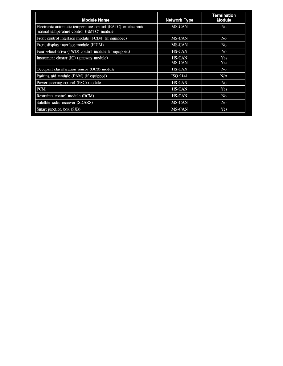
The MS-CAN is a medium speed communication network used for the following modules:
-
Audio unit
-
Electronic automatic temperature control (EATC) or electronic manual temperature control (EMTC) module
-
Front control interface module (FCIM)
-
Front display interface module (FDIM)
-
Instrument cluster
-
Satellite radio receiver (SDARS)
-
Smart junction box (SJB)
HS-CAN Network Operation
The HS-CAN network communicates using bussed messages. The HS-CAN network uses an unshielded twisted pair cable, data bus (+) and data bus
(-) circuits. In addition to scan tool communication, this network allows sharing of information between all modules on the network.
The HS-CAN is a high speed communication network used for the following modules:
-
ABS module
-
Four wheel drive (4WD) control module
-
Instrument cluster
-
Occupant classification sensor (OCS) module
-
Power steering control (PSC) module
-
PCM
-
Restraints control module (RCM)
Network Termination
The CAN network uses a network termination circuit to improve communication reliability. The network termination of the CAN bus takes place
inside the termination modules by termination resistors. Termination modules are located at either end of the bus network. As network messages are
broadcast, in the form of voltage signals, the network voltage signals are stabilized by the termination resistors. Each termination module has a 120
ohm resistor across the positive and negative bus connection in the termination module. With 2 termination modules on each network, and the 120
ohm resistors located in a parallel circuit configuration, the total network impedance, or total resistance, is 60 ohms.
Network termination improves bus message reliability by:
-
stabilizing bus voltage.
-
eliminating electrical interference.
