
Mariner 4WD L4-2.5L (2010)
Fan Clutch: Description and Operation
ENGINE CONTROL COMPONENTS
Cooling Fan Clutch
The cooling fan clutch is an electrically actuated viscous clutch that consists of 3 main elements:
-
a working chamber
-
a reservoir chamber
-
a cooling fan clutch actuator valve and a fan speed sensor (FSS)
The cooling fan clutch actuator valve controls the fluid flow from the reservoir into the working chamber. Once viscous fluid is in the working
chamber, shearing of the fluid results in fan rotation. The cooling fan clutch actuator valve is activated with a pulse width modulated (PWM) output
signal from the PCM. By opening and closing the fluid port valve, the PCM can control the cooling fan clutch speed. The cooling fan clutch speed is
measured by a Hall-effect sensor and is monitored by the PCM during closed loop operation.
The PCM optimizes fan speed based on engine coolant temperature (ECT), engine oil temperature (EOT), transmission fluid temperature (TFT),
intake air temperature (IAT), or air conditioning requirements. When an increased demand for fan speed is requested for vehicle cooling, the PCM
monitors the fan speed through the Hall-effect sensor. If a fan speed increase is required, the PCM outputs the PWM signal to the fluid port, providing
the required fan speed increase.
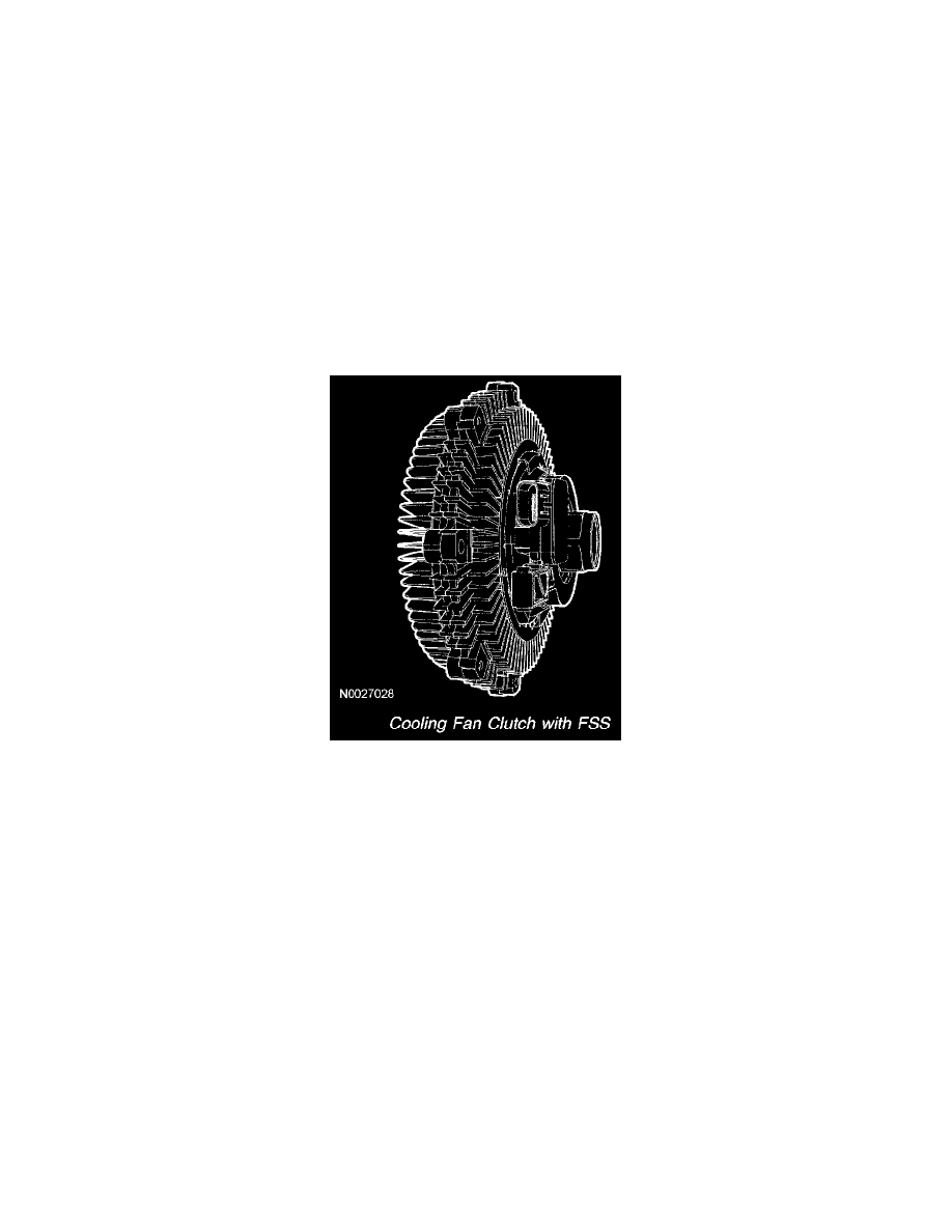
Cooling Fan Clutch With FSS