
Mariner 4WD L4-2.5L (2010)
NOTE: Failure to disconnect the battery when instructed will result in false resistance readings. Refer to Battery.
-------------------------------------------------
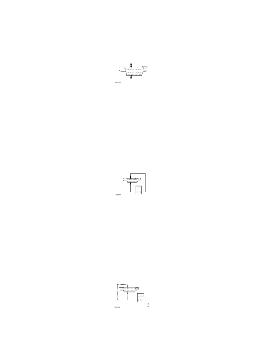
U1 CHECK THE DLC PINS FOR DAMAGE
-
Ignition OFF.
-
Disconnect the scan tool cable from the DLC.
-
Inspect DLC pins 3 and 11 for damage.
-
Are DLC pins 3 and 11 OK?
Yes
GO to U2.
No
REPAIR the DLC as necessary. CLEAR the DTCs. REPEAT the network test with the scan tool.
-------------------------------------------------
U2 CHECK THE MS-CAN TERMINATION RESISTANCE
-
Disconnect: Negative Battery Cable .
-
Measure the resistance between the DLC C251-3, circuit VDB06 (GY/OG), harness side and the DLC C251-11, circuit VDB07 (VT/OG), harness
side.
-
Is the resistance between 54 and 66 ohms?
Yes
GO to U3.
No
GO to Pinpoint Test V. See: Pinpoint Test V: No Medium Speed Controller Area Network (MS-CAN) Communication, All Modules Are Not
Responding
-------------------------------------------------
U3 CHECK THE MS-CAN (+) AND MS-CAN (-) CIRCUITS FOR A SHORT TO GROUND
-
Measure the resistance between the DLC C251-3, circuit VDB06 (GY/OG), harness side and ground; and between the DLC C251-11, circuit
VDB07 (VT/OG), harness side and ground.
-
Are the resistances greater than 1,000 ohms?
Yes