
Mariner 4WD L4-2.5L (2010)
-
Are the resistances greater than 1,000 ohms?
Yes
CONNECT the negative battery cable. GO to V33.
No
GO to V26.
-------------------------------------------------
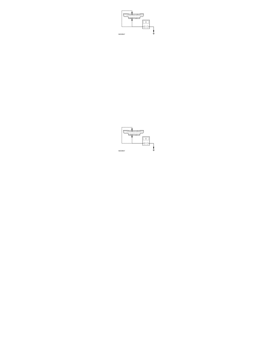
V26 CHECK THE MS-CAN (+) AND MS-CAN (-) CIRCUITS FOR A SHORT TO GROUND WITH THE IC DISCONNECTED
-
Disconnect: IC C220 .
-
Measure the resistance between the DLC C251-3, circuit VDB06 (GY/OG), harness side and ground; and between the DLC C251-11, circuit
VDB07 (VT/OG), harness side and ground.
-
Are the resistances greater than 1,000 ohms?
Yes
CONNECT the negative battery cable. GO to V34.
No
REPAIR the circuit. CONNECT all modules. CONNECT the negative battery cable. CLEAR the DTCs. REPEAT the network test with the scan tool.
-------------------------------------------------
V27 CHECK FOR CORRECT SJB OPERATION
-
Disconnect all the SJB connectors.
-
Check for:
-
corrosion
-
damaged pins
-
pushed-out pins
-
Connect all the SJB connectors and make sure they seat correctly.
-
Operate the system and verify the concern is still present.
-
Is the concern still present?
Yes
INSTALL a new SJB. REFER to Body Control Systems. CONNECT all modules. CLEAR the DTCs. REPEAT the network test with the scan tool.
No
The system is operating correctly at this time. The concern may have been caused by a loose or corroded connector. CONNECT all modules.
-------------------------------------------------
V28 CHECK FOR CORRECT GPSM OPERATION
-
Disconnect the GPSM connector.
-
Check for:
-
corrosion
-
damaged pins