
Mariner 4WD L4-2.5L (2010)
Remove and discard the 4 strut upper bushing nuts.
8. NOTICE: Do not allow the axle shaft to move outboard. Over-extension of the tripod Constant Velocity (CV) joint can result in the
separation of internal parts, causing failure of the axle shaft.
Remove the strut and spring assembly.
9. For additional information on the disassembly and assembly of the strut and spring assembly, refer to Strut and Spring Assembly See: Overhaul.
Installation
1. Position the strut and spring assembly upper mounting plate into the inner fender.
2. Align the 4 new strut upper bushing nuts to the reference marks.
-
Tighten to 47 Nm (35 lb-ft).
3. Install the 2 new strut-to-knuckle bolts and nuts.
-
Tighten to 115 Nm (85 lb-ft).
4. Install the new upper stabilizer bar link nut.
-
Tighten to 63 Nm (46 lb-ft).
5. Install the wheel speed sensor harness bolt.
-
Tighten to 15 Nm (133 lb-in).
6. Position the brake jounce hose to the bracket and install the brake jounce hose clip.
7. Check the front end alignment and adjust as necessary. For additional information, refer to Suspension &/or Alignment.
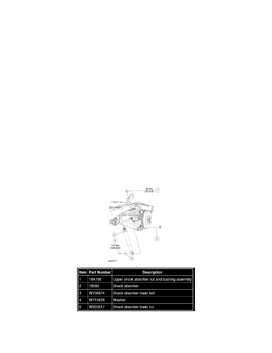
Rear Suspension
Shock Absorber
Removal and Installation
NOTICE: Suspension fasteners are critical parts because they affect performance of vital components and systems and their failure may result
in major service expense. New parts must be installed with the same part numbers or equivalent part, if replacement is necessary. Do not use a
replacement part of lesser quality or substitute design. Torque values must be used as specified during reassembly to make sure of correct