
Mariner 4WD L4-2.5L (2010)
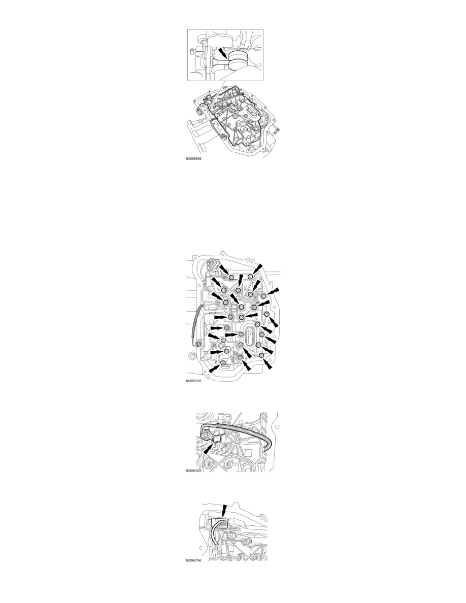
4. NOTICE: Make sure not to pinch the Output Shaft Speed (OSS) or Transmission Range (TR) sensor wiring harnesses when installing the
main control or damage to the sensors can occur.
NOTE: Install the different length bolts in the locations noted during disassembly.
Install the main control valve body, the main control valve body nut and the 22 main control valve body bolts. Tighten in a crisscross pattern.
-
Tighten to 10 Nm (89 lb-in).
5. Route the OSS sensor wiring harness and connect the electrical connector.
6. Connect the TR sensor electrical connector.
7. Install the main control cover grommet.