
Mariner 4WD L4-2.5L Hybrid (2009)
Valve Clearance: Adjustments
Valve Clearance Check
1. Remove the valve cover. For additional information, refer to Valve Cover See: Service and Repair/Removal and Replacement/Valve Cover.
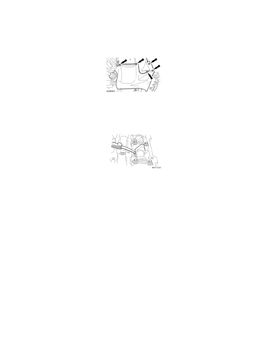
2. Remove the 5 bolts, the pin-type retainer (not shown) and the RH splash shield.
-
To install, tighten to 9 Nm (80 lb-in).
3. NOTE: Turn the engine clockwise only, and only use the crankshaft bolt.
NOTE: Before removing the camshafts, measure the clearance of each valve at base circle, with the lobe pointed away from the tappet. Failure to
measure all clearances prior to removing the camshafts will necessitate repeated removal and installation and wasted labor time.
Use a feeler gauge to measure the clearance of each valve and record its location.
4. NOTE: The number on the valve tappet only reflects the digits that follow the decimal. For example, a tappet with the number 0.650 has the
thickness of 3.650 mm.
NOTE: The nominal clearance is:
-
intake: 0.25 mm (0.0095 in).
-
exhaust: 0.30 mm (0.0115 in).
The acceptable clearances after being fully installed are:
-
intake: 0.22-0.28 mm (0.008-0.011 in).
-
exhaust: 0.27-0.33 mm (0.010-0.013 in).
Select tappets using this formula: tappet thickness = measured clearance + the existing tappet thickness - nominal clearance.
Select the closest tappet size to the ideal tappet thickness available and mark the installation location.
5. If any tappets do not measure within specifications, install new tappets in these locations. For additional information, refer to Valve Train
Components - Exploded View See: Camshaft, Lifters and Push Rods/Camshaft/Service and Repair/Removal and Replacement/Valve Train
Components - Exploded View and Valve Tappets See: Camshaft, Lifters and Push Rods/Lifter / Lash Adjuster/Service and Repair/Removal and
Replacement/Valve Tappets.