
Mariner 4WD V6-3.0L (2010)
2. Remove the Air Cleaner (ACL) and the ACL outlet pipe. For additional information, refer to Fuel Delivery and Air Induction.
3. Disconnect the master cylinder brake tube fittings from the HCU.
-
To install, tighten to 23 Nm (17 lb-ft).
Vehicles with 3.0L engine
4. Disconnect the master cylinder brake tube fittings from the master cylinder and remove the brake tubes.
-
To install, tighten to 23 Nm (17 lb-ft).
All vehicles
5. NOTE: The brake tubes must be installed in the same location as removed.
Disconnect the front brake tube fittings from the HCU.
-
To install, tighten to 15 Nm (133 lb-in).
6. Disconnect the rear brake tube fittings from the jumper tubes.
-
To install, tighten to 15 Nm (133 lb-in).
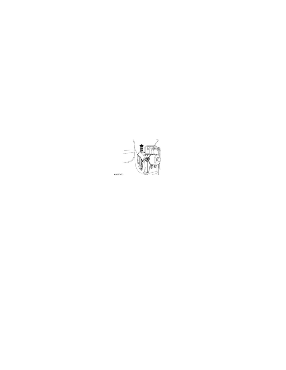
7. Disconnect the electrical connector by rotating the protective cover.
8. Remove the 3 HCU bracket-to-frame bolts and remove the HCU.
-
To install, tighten to 20 Nm (177 lb-in).
9. To install, reverse the removal procedure.
10. If a new ABS module was installed, download the module configuration information from the scan tool. For additional information, refer to
Information Bus.
11. If a new ABS module and/or a new HCU was installed, carry out the IVD Initialization sequence following the scan tool directions.
12. Bleed the brake system. For additional information, refer to Brakes and Traction Control.