
Mariner 4WD V6-3.0L (2010)
Brake Pedal Assy: Service and Repair
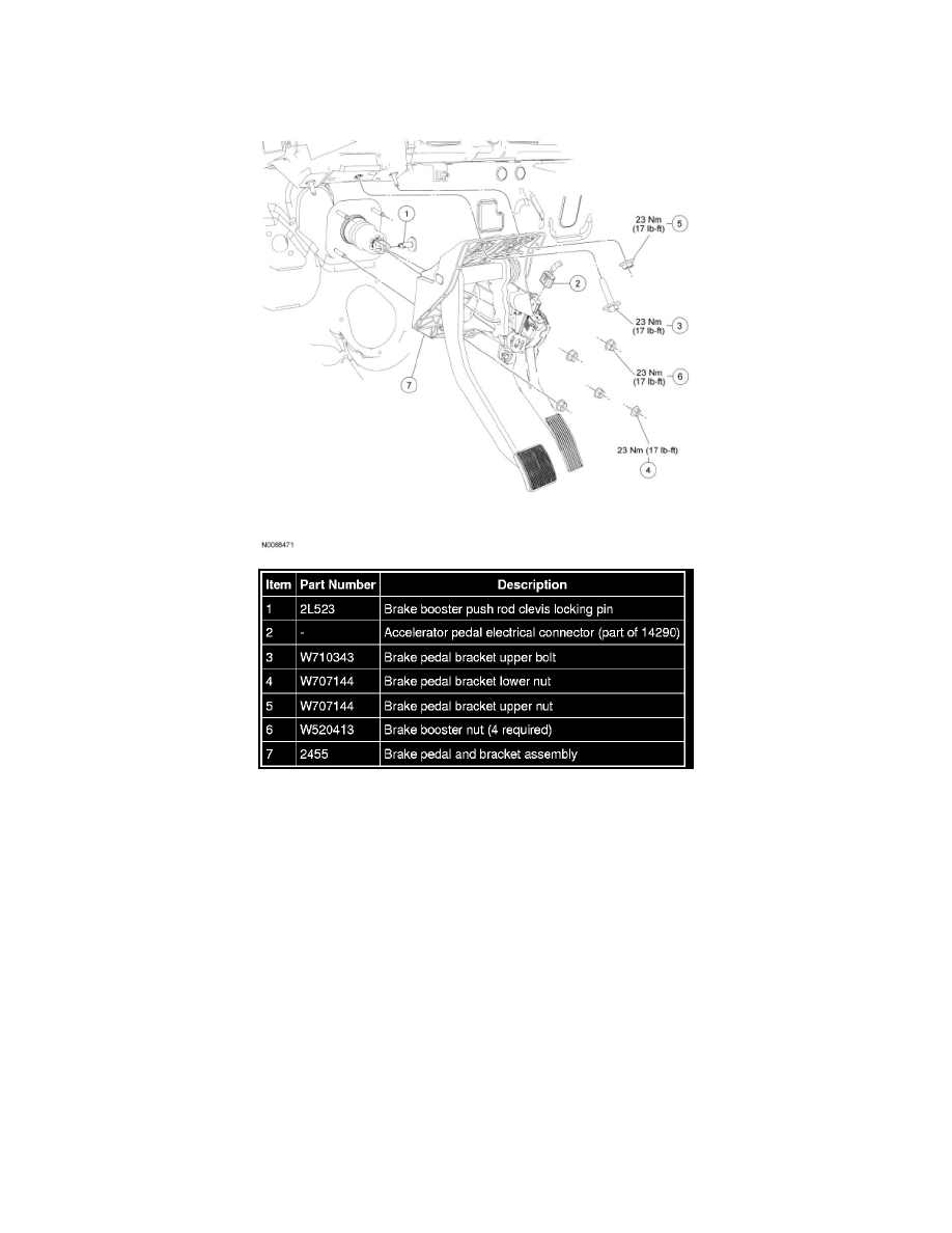
Brake Pedal and Bracket
Removal and Installation
1. NOTICE: Do not service the brake pedal or brake booster without first removing the stoplamp switch and speed control deactivator
switch. These switches must be removed with the brake pedal in the at-rest position. Switch plungers must be compressed for the switch
to rotate in the bracket. Attempting to remove the switch when the plunger is extended (during pedal apply) will result in damage to the
switch.
Remove the stoplamp switch.
2. NOTE: The booster push rod clevis locking pin is a one-time use only part. Any time the booster push rod clevis locking pin is removed, a new
booster push rod clevis locking pin should be used.
NOTE: Remove the clevis locking pin by squeezing the locking tabs and pulling outward on the opposite end.
Remove and discard the booster push rod clevis locking pin.
3. Disconnect the accelerator pedal electrical connector.
4. Remove the brake pedal bracket upper bolt.
-
To install, tighten to 23 Nm (17 lb-ft).
5. Remove the brake pedal bracket upper and lower nuts.
-
To install, tighten to 23 Nm (17 lb-ft).