
Mariner 4WD V6-3.0L (2010)
depower the system. The high-voltage hybrid system utilizes approximately 300 volts DC, provided through high-voltage cables to its components and
modules. The high-voltage cables and wiring are identified by orange harness tape or orange wire covering. All high-voltage components are marked
with high-voltage warning labels with a high-voltage symbol. Failure to follow these instructions may result in serious personal injury or death.
1. Verify the customer concern.
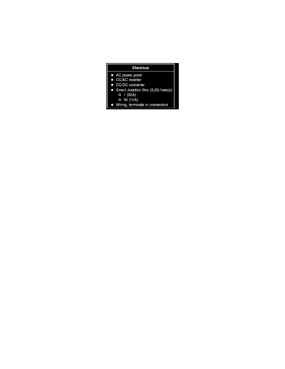
2. Visually inspect for obvious signs of electrical damage.
Visual Inspection Chart
3. If an obvious cause for an observed or reported concern is found, correct the cause (if possible) before proceeding to the next step.
4. If the cause is not visually evident, verify the symptom and GO to Symptom Chart. See: Symptom Related Diagnostic Procedures
5. If an obvious cause for an observed or reported concern is found, correct the cause (if possible) before proceeding to the next step.
6. NOTE: Make sure to use the latest scan tool software release.
If the cause is not visually evident, connect the scan tool to the Data Link Connector (DLC).
7. NOTE: The Vehicle Communication Module (VCM) LED prove out confirms power and ground from the DLC are provided to the VCM.
If the scan tool does not communicate with the VCM:
-
check the VCM connection to the vehicle.
-
check the scan tool connection to the VCM.
-
refer to Information Bus, No Power To The Scan Tool, to diagnose no power to the scan tool.
8. If the scan tool does not communicate with the vehicle:
-
verify the ignition is ON.
-
verify the scan tool operation with a known good vehicle.
-
refer to Information Bus to diagnose no response from the PCM.
9. Carry out the network test.
-
If the scan tool responds with no communication for one or more modules, refer to Information Bus.
-
If the network test passes, retrieve and record Continuous Memory Diagnostic Trouble Codes (CMDTCs).
10. Carry out the self-test diagnostics for the PCM.
11. If the DTCs retrieved are related to the concern, go to PCM DTC Chart. For all other DTCs, refer to Body Control Systems. See: Diagnostic
Trouble Code Descriptions
12. If no DTCs related to the concern are retrieved, GO to Symptom Chart. See: Symptom Related Diagnostic Procedures