
Mariner 4WD V6-3.0L (2010)
-
Front Display Interface Module (FDIM)
-
Global Positioning System Module (GPSM) (if equipped)
-
HVAC module (if equipped)
-
IC (gateway module)
-
Smart Junction Box (SJB)
Controller Area Network (CAN) Fault Tolerance
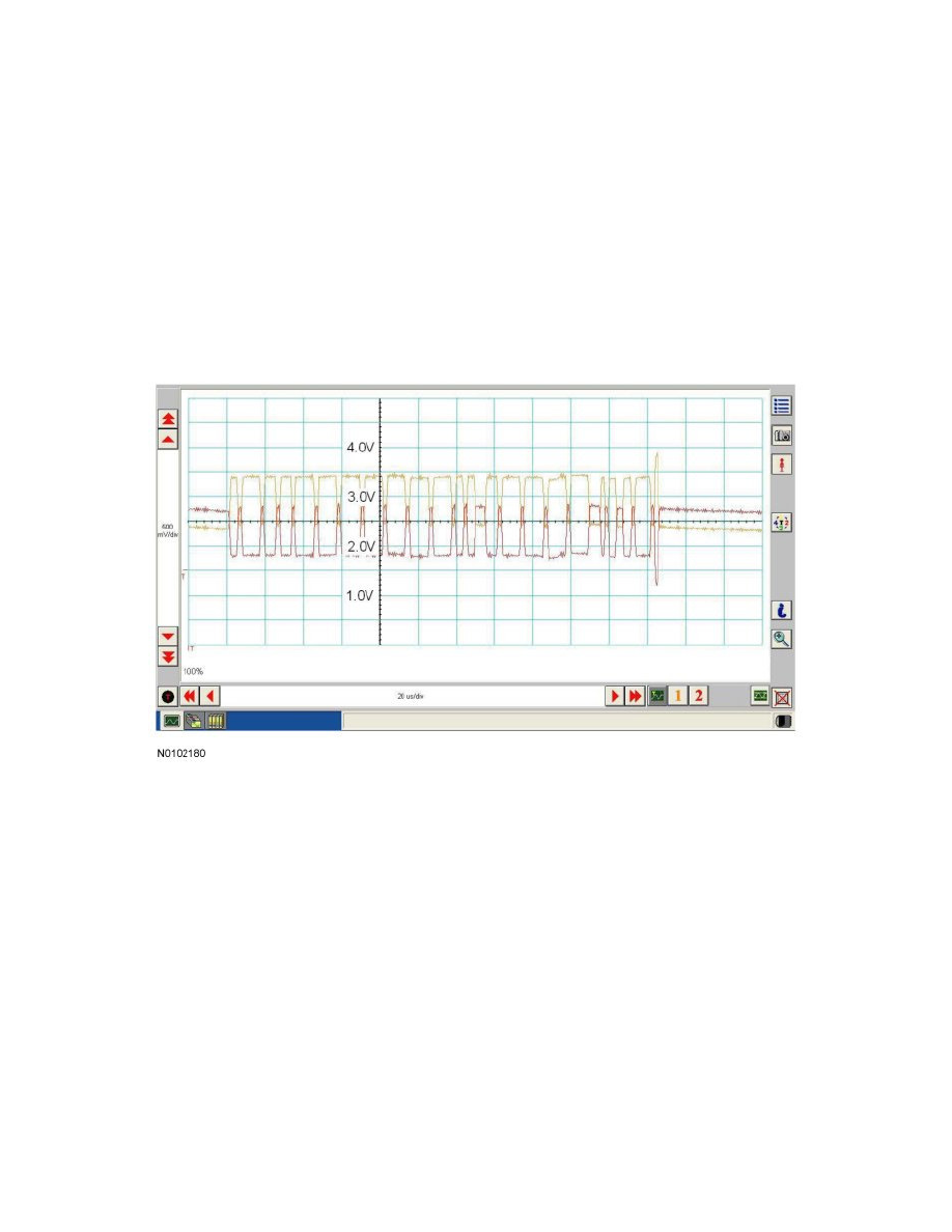
NOTE: The oscilloscope traces below are from the Integrated Diagnostic System (IDS) oscilloscope taken using the IDS pre-configured Controller
Area Network (CAN) settings. The traces are for both data (+) and data (-) taken simultaneously (2-channel) at a sample rate of 1 mega-sample per
second (1MS/s) or greater.
Traces below are viewed at 500mV per division (vertical axis) and 20 microseconds (20µs) per division (horizontal axis). Readings taken with a
different oscilloscope vary from those shown. Compare any suspect readings to a known good vehicle.
Normal CAN Operation
The data (+) and data (-) circuits are each regulated to approximately 2.5 volts during neutral or rested network traffic. As messages are sent on the data
(+) circuit, voltage is increased by approximately 1.0 volt. Inversely, the data (-) circuit is reduced by approximately 1.0 volt when a message is sent.
Successful communication of a message can usually be identified by the slight spike at the end of a message transmission. Any signals that are
significantly different than the normal CAN waveform may cause network DTCs (U-codes) to set or may cause a complete network outage.
CAN Circuits Shorted Together