
Mariner 4WD V6-3.0L (2010)
-
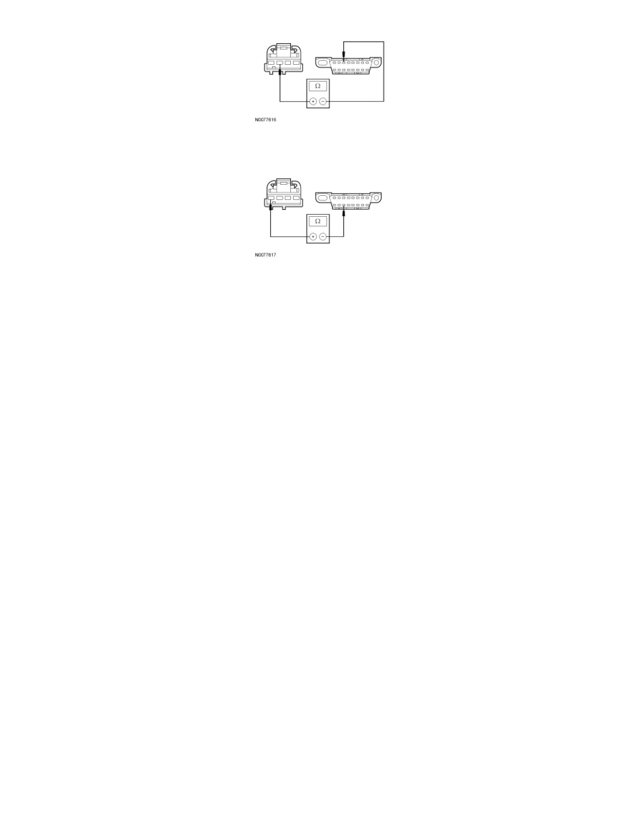
Measure the resistance between the FCIM C2402-4, circuit VDB07 (VT/OG), harness side and the DLC C251-11, circuit VDB07 (VT/OG),
harness side.
-
Are the resistances less than 5 ohms?
Yes
CONNECT the negative battery cable. GO to O4.
No
REPAIR the circuit in question. CONNECT the negative battery cable. CLEAR the DTCs. REPEAT the network test with the scan tool.
-------------------------------------------------
O4 CHECK FOR CORRECT FCIM OPERATION
-
Disconnect the FCIM connector.
-
Check for:
-
corrosion
-
damaged pins
-
pushed-out pins
-
Connect the FCIM connector and make sure it seats correctly.
-
Operate the system and verify the concern is still present.
-
Is the concern still present?
Yes
INSTALL a new FCIM. REFER to Accessories and Optional Equipment. CLEAR the DTCs. REPEAT the network test with the scan tool.
No
The system is operating correctly at this time. The concern may have been caused by a loose or corroded connector.
-------------------------------------------------
Pinpoint Test P: The Audio Control Module (ACM) Does Not Respond To The Scan Tool
Communications Network
Pinpoint Tests
Pinpoint Test P: The Audio Control Module (ACM) Does Not Respond To The Scan Tool
Refer to Wiring Diagram Set 14 (Escape/Mariner, Escape Hybrid/Mariner Hybrid), Module Communications Network for schematic and connector
information. See: Diagrams/Electrical Diagrams/Diagrams By Number
Refer to Wiring Diagram Set 130 (Escape/Mariner, Escape Hybrid/Mariner Hybrid), Audio System/Navigation for schematic and connector information.
See: Diagrams/Electrical Diagrams/Diagrams By Number