
Mariner 4WD V6-3.0L (2010)
anti-rotation key has been removed before installing the steering wheel, the clockspring must be centered. Failure to follow this instruction may
result in component damage and/or system failure.
Install the clockspring and 2 screws.
2. Connect the clockspring electrical connector.
3. Install the lower steering column shroud and 3 screws.
4. Attach the upper steering column shroud to the lower steering column shroud.
5. WARNING: If the clockspring is not correctly centralized, it may fail prematurely. If in doubt, repeat the centralizing procedure. Failure
to follow these instructions may increase the risk of serious personal injury or death in a crash.
NOTICE: Do not over-rotate the clockspring inner rotor. The internal ribbon wire is connected to the clockspring rotor. The internal
ribbon wire acts as a stop and can be broken from its internal connection. Failure to follow this instruction may result in component
damage and/or system failure.
If a new clockspring was installed and the anti-rotation key has not been removed proceed to Step 7.
If a new clockspring was installed and the anti-rotation key has been removed before the steering wheel is installed or the same clockspring is
being installed, rotate the clockspring inner rotor counterclockwise and carefully feel for the ribbon wire to run out of length with slight
resistance. Stop rotating the clockspring inner rotor at this point.
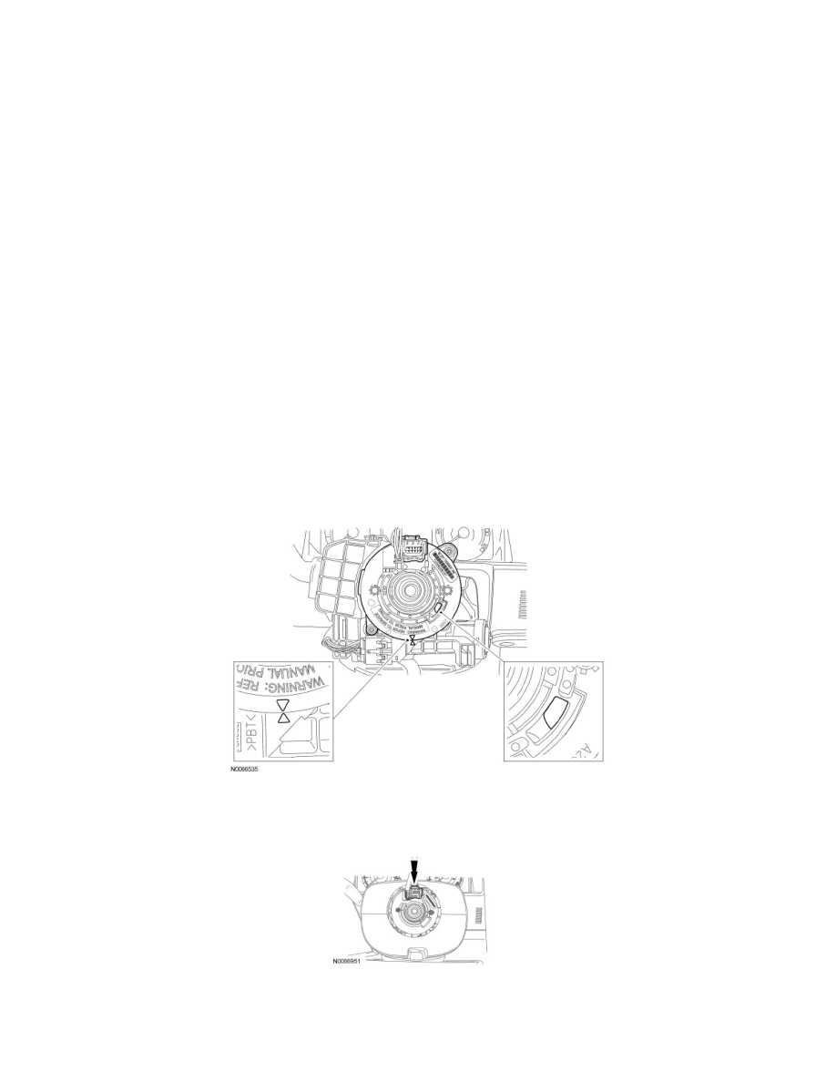
6. Starting with the clockspring inner rotor, wiring and connector in the 12 o'clock position, rotate the inner rotor clockwise through 4 revolutions to
center the clockspring.
Verify that the clockspring is correctly centered by observing that after 4 revolutions:
-
the clockspring rotor window is in the 4 o'clock position and the yellow indicator shows in the window.
-
the 2 arrows located on the inner and outer rotor of the clockspring line up in the 6 o'clock position.
-
the clockspring inner rotor, wiring and connector are in the 12 o'clock position.
7. NOTICE: To prevent damage to the clockspring, make sure the road wheels are in the 12 o'clock position to install the steering wheel.
Install the steering wheel.
8. If a new clockspring was installed, remove the anti-rotation key.