
Merkur Xr4ti L4-140 2.3L SOHC Turbo (1985)
Brake Rotor/Disc: Service and Repair
Removal and Installation
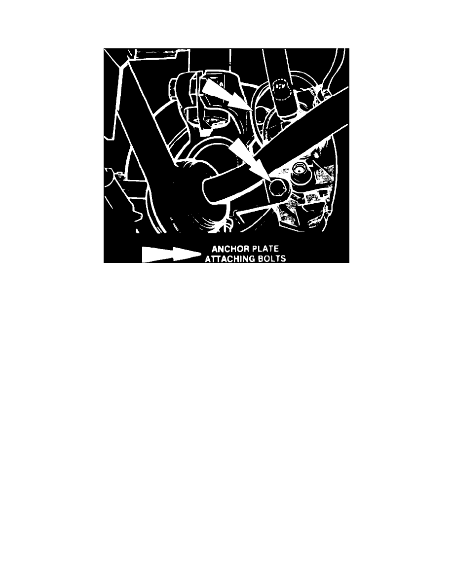
Fig. 2 Location of anchor plate attaching bolts. XR4Ti
1.
Raise and support vehicle, then remove wheel assembly.
2.
Remove anchor plate attaching bolts, Fig. 2.
3.
Lift caliper and anchor plate assembly off rotor and tie out of way.
4.
Remove rotor retaining clip and the rotor.
5.
Reverse procedure to install, torquing anchor plate to spindle carrier attaching bolts to 43-44 ft. lbs. The hub and rotor are a matched and
balanced assembly. Before removing rotor locate the paint mark or etch mark that indicates proper hub to rotor alignment. If marks are
not present, mark hub and rotor for assembly alignment.
6.
If rotor has been removed without alignment marks, proceed as follows:
a. Install rotor on hub and install wheel lug nuts.
b. Using dial indicator with suitable holding fixture, measure rotor runout. The indicator stylus should contact the rotor approximately {7/16}
inch from the end.
c. Rotate hub and disc assembly and record dial indicator reading.
d. If indicator reading is .003 inch or less, this positioning of rotor may be used during assembly.
e. If indicator reading is greater than .003 inch, reposition rotor on hub in 90 degree increments until lowest reading is obtained.
f.
When a reading of no more than .003 inch is obtained, mark alignment of hub and rotor.