
Merkur Xr4ti L4-140 2.3L SOHC Turbo (1985)
Overboost Switch: Testing and Inspection
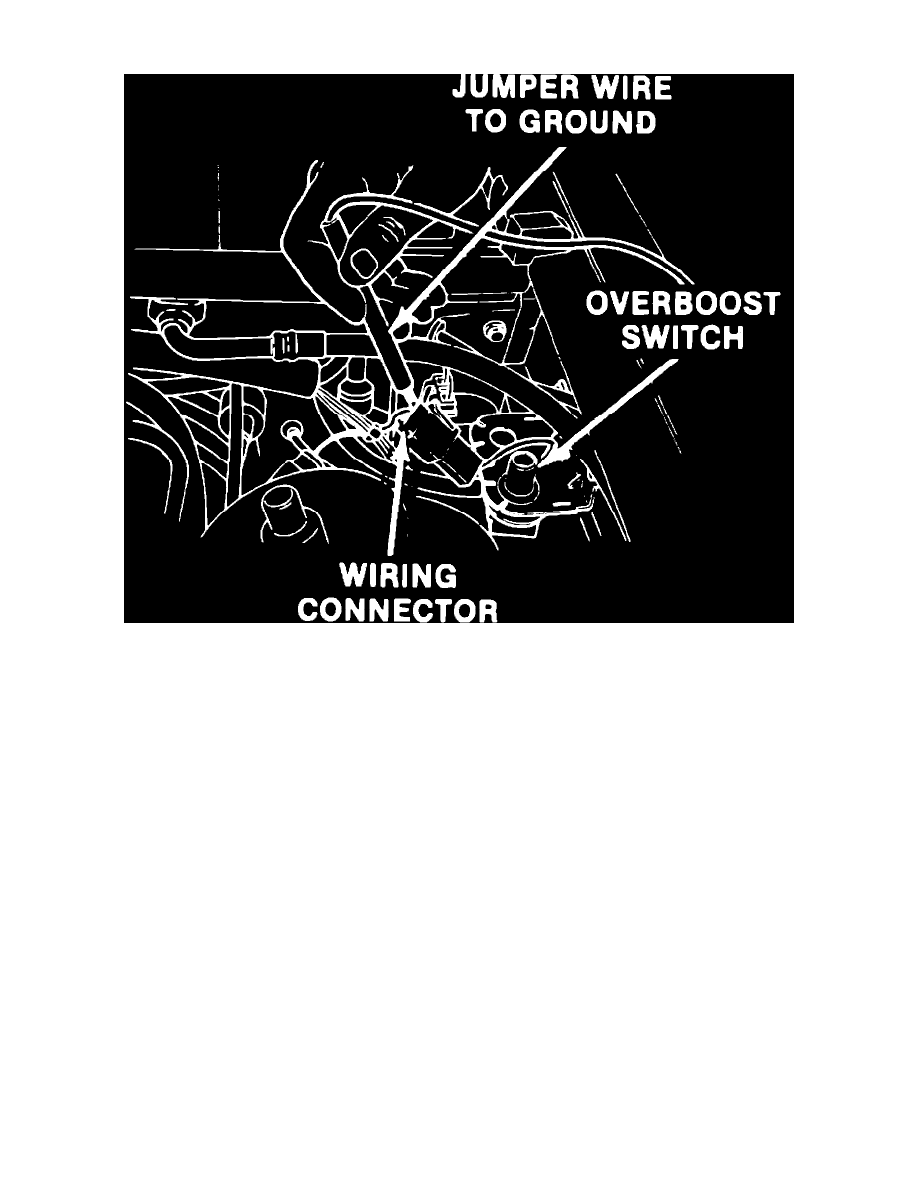
Fig. 4 Checking operation of overboost warning switch buzzer
TEST 1, BUZZER OPERATIONAL CHECK
1.
Connect jumper wire from switch connector to clean ground, Fig. 4.
2.
If buzzer sounds, proceed to TEST 4.
3.
If buzzer does not sound, proceed to TEST 2.
TEST 2, BUZZER TO SWITCH CONTINUITY CHECK
1.
Disconnect wiring connectors at overboost switch and buzzer.
2.
Using ohmmeter, check for continuity in circuit 31-14 (BR/Y), buzzer connector to switch connector. Overboost buzzer is located behind right
side of instrument panel.
3.
If there is continuity, proceed to TEST 3.
4.
If there is no continuity, repair open in circuit, then repeat TEST 1 to verify buzzer operation.
TEST 3, POWER FEED TO BUZZER CHECK
1.
Using test light, check for battery voltage at buzzer power feed terminal, circuit 54-14 R/BL.
2.
If test light illuminates, replace buzzer, then verify operation of new buzzer.
3.
If test light does not illuminate, repair open in power feed circuit, then verify operation of buzzer.
TEST 4, GROUND WIRE INSPECTION
1.
Inspect ground wire from bottom of switch to bracket for damage or poor connection.
2.
If ground wire is satisfactory, proceed to TEST 5.
3.
If ground wire is unsatisfactory, repair as necessary, then verify buzzer operation.
TEST 5, GROUND CIRCUIT CHECK